background image


Manual Part # 800-1070-001, Rev G, 10-2008 

Page 6 of 16 

S

ECTION 

2


I

NSTALLATION


Assembly & Mounting 

Digi-Stop is easy to install. By following the basics of good installation reliable, 
error-free operation can be expected.   
 
1.  Carefully slide the encoder onto the Scale. 
 
2.  Loosen the locking knob and slide the Stop assembly into the fence 

extrusion. 

 
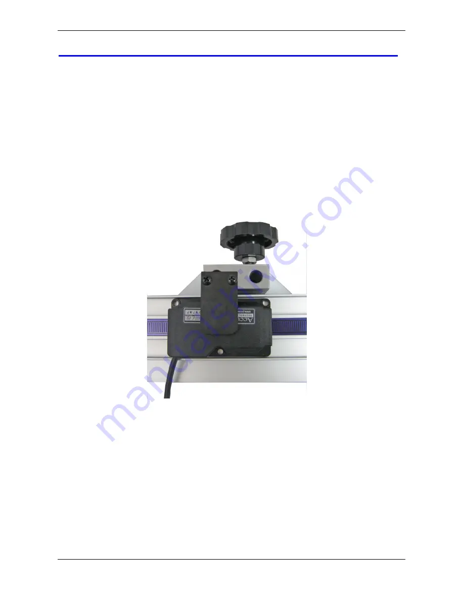
3.  Position the encoder and Stop together and slide the encoder under  the 

Guide Clip so the post on the encoder is captured in the slot of the Guide 
Clip, as shown below 


4.  Attach the readout to the aluminum block on the stop using the enclosed 

strips of Velcro.  Plug the encoder into the readout .  

 
5.  Position the fence system so it is 90 degrees with respect to the blade and 

bolt it to your table by inserting the included nuts into the T slot on the 
bottom of the fence extrusion and using the bolts to mount the fence to 
your table from the bottom. 

 
6.  Move the stop assembly left to right and note if the readings increase or 

decrease.  Depending upon the installation (left or right infeed), it may be 
necessary to reverse the reading direction.   

See


Section 3: 

Reverse Readings


Summary of Contents for Digi-Stop

Page 1: ...User Manual for Digital Readout Firmware version d 2 000 Higher Digi Stop Digi Stop ...

Page 2: ...tness for a particular purpose except as expressly provided in this agreement Accurate Technology Inc shall not be liable for any special incidental or consequential damages or for loss damage or expense directly or indirectly arising from the customer s use of or inability to use the equipment either separately or in combination with other equipment or for personal injury or loss or destruction o...

Page 3: ...ion 7 Maintenance 7 Changing the Batteries 8 The LCD Display 8 SECTION 3 OPERATION 9 Readout Keys 9 Key Timing 9 On Off 9 Units 9 DATUM and 10 Readout Resolution 10 Readout Lock Mode 11 Making Incremental Measurements 11 Reverse Readings 10 Circuit board Jumpers 12 Readout Programming 13 Programming Parameters 14 Pr 1 Datum Key 14 Pr 2 Reverse Readings 14 Pr 3 Key Lockout 14 Pr 4 Readout Resolutio...

Page 4: ...s It is immune to dirt sawdust or other non conductive contaminants making it the ideal choice for woodshops and other dusty environments What This Manual Includes This manual includes information for Digi Stop 4 Part Number 903 6004 020 Digi Stop 8 Part Number 903 6008 020 Digi Stop 10 Part Number 903 6010 020 Digi Stop Specifications Measuring Range 52 96 inches or 116 inches Accuracy 015inch Re...

Page 5: ...on with the Scale attached The second package contains the Digital Stop and some installation hardware Pictured below are parts that will be referred to throughout this manual Scale Encoder Guide Clip Digi Stop End View shading shown is for clarity only Stop Lock Knob Readout Guide Clip Encoder Fence Adjustable Wing Digital Readout Stop ...

Page 6: ...captured in the slot of the Guide Clip as shown below 4 Attach the readout to the aluminum block on the stop using the enclosed strips of Velcro Plug the encoder into the readout 5 Position the fence system so it is 90 degrees with respect to the blade and bolt it to your table by inserting the included nuts into the T slot on the bottom of the fence extrusion and using the bolts to mount the fenc...

Page 7: ...desired This prevents accidentally re zeroing during normal use See Section 3 Readout Lock Mode Maintenance The fence extrusion should be cleaned of debris periodically Do not use any liquid lubricants on the scale as this may impede the encoder s ability to operate properly and attract other contaminants to the scale If the stop becomes difficult to move and the fence and scale have both been cle...

Page 8: ...kaline batteries noting the proper orientation Replace the cover and tighten the screws CAUTION DO NOT BEND THE BATTERY CLIPS THESE CLIPS ARE DESIGNED TO BE LOOSE WHEN THE CASE IS OPEN AND WILL COMPRESS AND SECURE THE BATTERIES IN PLACE WHEN THE CASE HALVES ARE SCREWED TOGETHER The LCD Display The above figure illustrates all the segments available on the LCD Not all segments are used on Digi Stop...

Page 9: ... quickly become intuitive On Off Momentarily pressing the ON OFF key will cause the readout to turn on or off The Firmware Version of the readout is displayed on power up when ON OFF key is used While the readout is on if the stop is not moved for 15 minutes the readout will automatically turn itself off to conserve battery life While it is off if the stop is moved as little as 002in 05mm or the O...

Page 10: ...y a user programmed value Programming Parameter Pr1 Momentarily depressing the key increments the current position by one unit of measurement Momentarily depressing the key decrements the current position by one unit Pressing and holding the or keys will cause the displayed position to change continuously Holding down the key will cause the amount of change to speed up This allows for quick adjust...

Page 11: ...The display of fractions remains the same for all settings 1 16 1 32 1 64 See Section 3 Readout Programming Programming Parameter Pr4 Making Incremental Measurements The readout has two measurement modes or indexes One is referred to as ABS or Absolute and the other as INC or Incremental The absolute measurement mode allows the operator to read the current position of the stop referenced from a fi...

Page 12: ...ing mode the UNITS key no longer functions to change the measurement units displayed The absolute position of the Digi Stop is not lost when using the incremental mode When the readout is switched back to the absolute mode the readout reflests the current stop position relative to your original calibrated absolute setting Circuit board Jumpers The Digi Stop readout has several user configurable ju...

Page 13: ... number then the currently programmed value Moving down parameter list Press and hold the ON OFF key and momentarily press the UNITS key to move backward through the Programming list Increase parameter value Momentarily press the PLUS key while displaying a Programming Parameter Value to increase the setting Decrease parameter value Momentarily press the MINUS key while displaying a Programming Pa...

Page 14: ...itive vs negative when the stop is moved Default 0 Pr 3 Key Lockout 0 or 1 This parameter controls the operation of the and DATUM keys If enabled set to 1 these keys will not function and the LOCK LOCK LOCK LOCK symbol will appear on the display This prevents accidental changes when pressing these keys during normal operation Default 0 Pr 4 Readout Resolution 1 2 3 This parameter sets the number o...

Page 15: ...readout no Enc no Enc no Enc no Enc will appear on the display To clear Be sure the encoder is on the scale and plugged into the readout The battery clips seem to be very loose Is this normal Yes DO NOT attempt to bend these clips or wedge anything between them and the case These clips are designed to expand when the two case halves are screwed together The readings are backwards You can change re...

Page 16: ...CAN MADE PRODUCT Accurate Technology Inc 270 Rutledge Rd Unit E Fletcher NC 28732 USA 828 654 7920 Please register your product at http www digi kit com registration htm This manual is available online at www digi kit com Manual P N 800 1070 001 Rev G Copyright Accurate Technology 2008 ...

Reviews: