background image

Quick Start Pinpointer Pro

PC Brand Subject to Change Without Notice

Getting Started

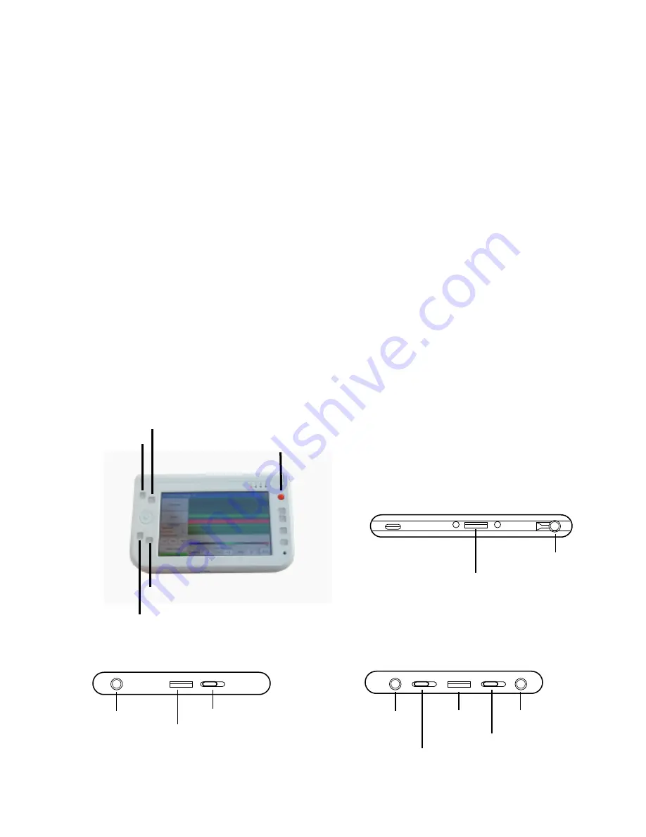
Mouse right click

Mouse left click

Left Edge View

Right Edge View

Front Edge View

Front view

...

...

. .

WLAN On/Off

USB Port

DC In

Stick point (Mouse or touch pad)

Audio In/Out

Volume Up/Down

USB Port

Power Hold

SAS

Stylus Compartment (pen)

Docking Port

Training

Training is available with the purchase of a unit, and one hour of technical assistance is 
offered after purchase.

Software

The software included with the PINPOINTER PRO is installed and ready to go to work for 
you.

Quick Start Procedure

1. With the cable supplied plug the USB end into PC USB port (left edge view) then plug 
    the other end of the cord into antenna 
2. Turn on UMPC or laptop computer (left edge view) and start software 
3. Allow a few moments for the programs to communicate with each other
    A. Click on recommended resolution of 800X480 (if not preset)
    B. Using stick point button or stylus move over Pinpoint file and left click (front view)
4. When it’s ready, click Connect then click Start, now you may begin scanning 
5. Keep antenna pointing down (vertical) as close to the ground as possible and in the 
    same direction, without rotating the antenna for best results.

Software Keyboard

Launch Pad

Detailed PC information supplied on pages 4 and 5

3

Summary of Contents for Pinpointer Pro

Page 1: ......

Page 2: ...Started PC Set Up Ground Balancing and Scan Methods Scan Methods and Samples Scan Samples Scan Samples Scan Sample and Pinpointer Pro Options Trouble shooting Warranty 2 3 4 5 6 7 8 9 10 11 Accurate...

Page 3: ...with all USA IMAGER SYSTEMS Antenna Cord Computer It s that simple 2 The PINPOINTER PRO is a stand alone unit The control unit is in the antenna just plug the USB cable into the computer plug the othe...

Page 4: ...or you Quick Start Procedure 1 With the cable supplied plug the USB end into PC USB port left edge view then plug the other end of the cord into antenna 2 Turn on UMPC or laptop computer left edge vie...

Page 5: ...scanning a small difference in the numbers can mean a target is detected Current The current reading is where the antenna is reading at the time The current current signal strength reading can assist...

Page 6: ...r an organized accurate scan with a GPS the grid can be laid out on it To continue a grid scan return to the beginning point and move to the right of that point about 2 ft or less increments and repea...

Page 7: ...umbers that is the indicator The monitor will show red when detecting a metallic object and blue will be a void a negative or milligauss reading when the values are set correctly When a target is loca...

Page 8: ...6 8 10 12 South to North Travel Tire Rim Buried 6 ft Deep 0 1 1 3 7 2 4 0 0 2 4 6 8 10 12 North to South Travel 0 1 0 3 1 1 1 0 0 2 4 6 8 North to South Travel 0 1 13 1 1 PVC Buried 2 ft Deep Note can...

Page 9: ...d 0 2 4 6 8 10 12 South to North Travel 0 1 3 7 2 2 1 0 2 4 6 8 10 12 North to South Travel 0 1 1 3 7 1 2 1 0 2 4 6 8 North to South Travel 0 2 9 1 1 1 Hammer Head Buried below concrete floor Copper A...

Page 10: ...ntrols for adjusting the contrast brightness tint and color of the image The miniature controls and battery are integrated in a lightweight sleek system that is easily clipped to a belt or carried in...

Page 11: ...attempting to read on a different day or even a different time of day the ground moisture content can effect scan readings Another cause of different readings may be your shoes may have metal on them...

Page 12: ...TED IN DURATION TO THE DURATION OF THIS WARRANTY Some States Jurisdictions do not allow limitations on how long an implied warranty or condition lasts or exclusions or limitations of consequential or...

Reviews: