background image

AM8060 Precision Thermometer User’s Guide                                    


19/41 

5.1.7


It is required to wait for 10 seconds for the data to be stable. 
Each second is shown with a blinking dot at the top left hand 
corner of the display. Once this is completed, the next step 
involves saving the calibrated data. To save the data, press the 

MENU

 key and the third line of data will blink to indicate the 

option to save. 

5.1.8


To save this calibration value, press and hold the 

 key and 

then press the 

key. This will store the calibration data to the 

instrument, and the program will go back to the main menu 
(*CALIBRATION MENU*). If users DO NOT want to save the 

data, press the 

MENU

 key and bring the program back to main 

menu ( *CALIBRATION MENU*). 

5.2


 25 Ω calibration 

5.2.1


The process of 

25


Ω calibrations is similar

 to t

hat of 100 Ω 

calibrations. First, turn off the power of the instrument and 
ensure the measurement/calibration switch at the rear panel is 
moved to the “CAL” side (right side), as shown in Figure 3. 
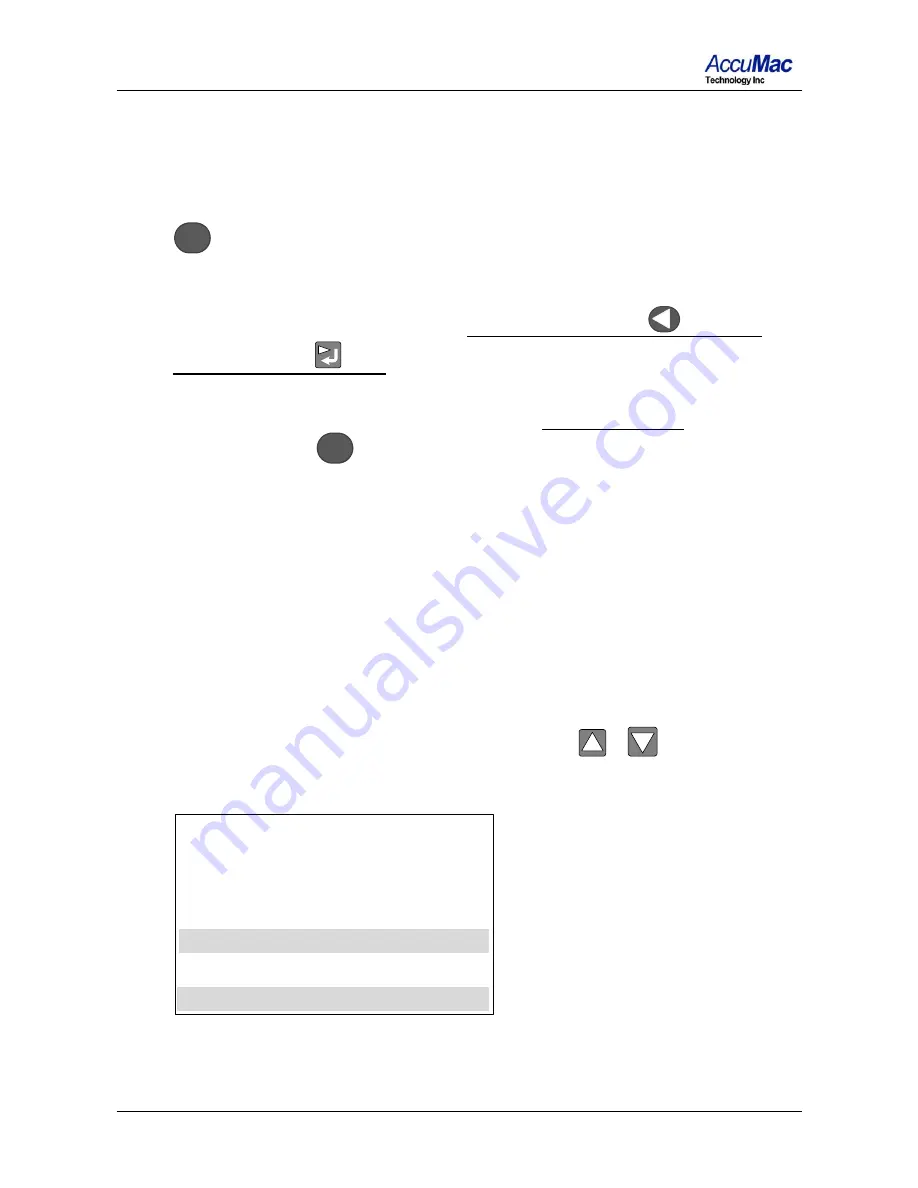
5.2.2


Choose the 25 Ohm CALIBRATION under main menu 

(*CALIBRATION MENU*) by touching 

or

 key to move 

the “>” to the “25 Ohm CALIBRATION” line


* CALIBRATION MENU

     100 Ohm CALIBRATION

 >   25 Ohm CALIBRATION

                               Enter = Yes 

-------------------------------------------


Summary of Contents for AM8060

Page 1: ...Rev 202001V1 AM8060 Precision Thermometer User s Guide Please download the latest version at www accumac com...

Page 2: ...panel display and touchpad 7 4 4 Selecting Units 9 4 5 Selecting Sensors Probes and Adjusting Parameters 9 5 Instrument Calibration And Accuracy Adjustments 16 5 1 100 calibration 17 5 2 25 calibrati...

Page 3: ...ch must be at the measurement left position Loss of calibration data will occur if the switch is at the calibration CAL position when the instrument is used in measurement application The instrument i...

Page 4: ...that can do plug and record With these flexible peripherals temperature data can be easily captured and saved in real time 1 1 Main Application Temperature measurement with standard platinum resistanc...

Page 5: ...8060 Precision Thermometer User s Guide 4 41 Wireless real time temperature data capturing with optional external wireless module optional Real time temperature data capturing and saving to flash driv...

Page 6: ...C 0 009 C 232 C 0 015 C 420 C 0 015 C 420 C 0 025 C 660 C 0 020 C 660 C 0 025 C 850 C Short term stability o 0 001 C with 100 platinum probe o 0 003 C with 25 platinum probe Working environment 15 C...

Page 7: ...ording Start Stop button Left key Value Adj Right Return Key Figure 1 Front Panel Rear Panel U Drive Interface Probe 1 S1 terminals AC Power Inlet Switch USB Measurement Probe 2 S2 terminals Calibrati...

Page 8: ...perature measurement Figure 3 shows the rear panel of the AM8060 Probe 1 can be connected to terminals marked with S1 and Probe 2 to S2 Figure 3 Rear Panel and Probe Terminals 4 2 Instrument connectio...

Page 9: ...connected via its USB client interface Line 2 which is indicated with t1 shows the measured temperature of Probe 1 S1 The SPRT at the end of the Line 2 tells the type of probe of Probe 1 S1 The AM8060...

Page 10: ...the probes The menu key MENU and return right shift key can be used for probe selections and parameter adjustments The probes compatible with AM8060 are 25 or 100 SPRTs or 25 or 100 Secondary PRTs or...

Page 11: ...cording to ITS 90 standard platinum resistance thermometer equations 4 5 2 Selecting Sensors Probe and Parameters Input 4 5 2 1 To select the type of sensor press MENU key and then hold key After 3 se...

Page 12: ...ess or key to move the selection line with the symbol to Sensor 1 Setting Press key to enter the Sensor 1 setting adjustment program as shown below The probe type can either be IPRT or SPRT Users can...

Page 13: ...e range parameters b and c can be 0 for some instances Please refer to ITS 90 for more information If the sensor type is IPRT the adjustable parameters are R0 A B and C SENSOR 1 IPRT SET A MENU Exit E...

Page 14: ...the Rtp adjustment program SENSOR 1 SPRT MENU Exit v Adj Rtp OHM 25 5260 The instrument will display the current Rtp value The digit underlined with the blinking bar indicates the adjustable position...

Page 15: ...ment is different from Rtp as the value of a4 can be 0 If a4 is 0 the user can move the cursor by using and keys to SET A4 0 line and press the key to confirm the selection If a4 is a value other than...

Page 16: ...a change has been made To save the changes press key otherwise press MENU key and the program will go back to the previous screen 4 5 2 11 Other parameter adjustments are similar to the above Rtp and...

Page 17: ...is recommended Users can calibrate AM8060 using standard resistors with calibrated values Warning It is required to set correct R0 or Rtpw values in Sensor 1 S1 before calibrations To calibrate AM8060...

Page 18: ...ALIBRATION and 25 Ohm CALIBRATION The following is an illustration of 100 Ohm CALIBRATION CALIBRATION MENU 100 Ohm CALIBRATION 25 Ohm CALIBRATION Enter Yes 5 1 3 Use or key on the keypad to select the...

Page 19: ...ting while the resistance is calibrated When the process is finished the screen will display the result as seen below 100 Ohm CALIBRATION 100 0238 Rt 111 0000 OHM Menu Exit v Adj 100R Rs OHM 5 1 6 To...

Page 20: ...ore the calibration data to the instrument and the program will go back to the main menu CALIBRATION MENU If users DO NOT want to save the data press the MENU key and bring the program back to main me...

Page 21: ...resistance close to 25 otherwise the calibration will not be accurate 5 2 5 Touch key to start the 25 calibration The instrument will display Waiting for a few seconds while the resistance is calculat...

Page 22: ...instrument To start the data saving touch the MENU key and the third line of data will blink to indicate the option to save 5 2 8 To save this calibration press and hold the key and then press the ke...

Page 23: ...AM8060 W precision thermometer with embedded wireless function Wireless Transceiver USB cable with length of 2m to 5m Computer with USB interface and Windows operating system Figure 4 AM8060 Wireless...

Page 24: ...system The detailed instructions for this are shown in the Appendix 5 After the installation of the USB driver the user will need to install the free software on the CD included with the AM8060 Insert...

Page 25: ...rwise the wireless signal is too weak and the link is not stable To increase the strength of the wireless connection users can move the AM8060 closer to the computer or increase the height of the Cool...

Page 26: ...adjust the data sampling rate by typing in an integer into the box Every x Sec below Data Saving X indicates the sampling period in the unit of seconds The sampling period can be adjusted only when t...

Page 27: ...26 84 456 79 930 16 23 20 4 526 84 456 79 930 16 23 21 4 526 84 456 79 930 end recording Time t1 C t2 C t1 t2 C 10 48 45 4 526 84 456 79 930 10 48 49 4 526 84 456 79 930 end recording The first column...

Page 28: ...is pressed the data saving will be halted and the phrase end recording will be added to the file To continue data saving users can click on REC and new data will be added to the last line of the prev...

Page 29: ...he flash drive is connected the display will say Device Detected D p to indicate that the flash drive is detected The top left hand corner of the display should display UDr to remind users that a flas...

Page 30: ...e file when REC key has been turned off Time t1 t2 t1 t2 0 23 4 525 529 475 534 000 1 44 4 524 529 475 534 000 2 64 4 524 529 475 533 999 3 85 4 524 529 475 533 999 5 05 4 524 529 475 534 000 6 26 4 5...

Page 31: ...e Setting Sensor1 Setting Sensor2 Setting B Press key or key to move the cursor line with sign to U Drive Setting then press key to go to the Record Cycle adjustment program as seen below N represents...

Page 32: ...ample the above picture shows the new N value as 9 which means the AM8060 will save data to the file every 9x1 21 seconds To save this value press and hold key and then press key If users DON T want t...

Page 33: ...AM8060 Precision Thermometer User s Guide 32 41 Note The parameter adjustments should only be performed while the flash drive is not in the data saving process...

Page 34: ...the AM8060 digital thermometer to a computer Figure 5 AM8060 USB Temperature Data Acquisition System 2 The first time the AM8060 digital thermometer is connected to a computer the computer will requir...

Page 35: ...instructions below detail how to adjust the sampling period Find the Every x Sec section of the Data Saving section at the right side of the software s GUI The unit of the sampling period is seconds I...

Page 36: ...ND or Stop and the temperature data saving will be stopped The following figure shows that the data is saved to file with a sampling period of 3 seconds Data saved in U_x2data txt will appear in the f...

Page 37: ...installation of USB drivers are required the first time these instruments are connected to a computer The USB drivers for the AM8060 precision thermometer and Wireless Transceiver are the same The fol...

Page 38: ...ometer User s Guide 37 41 3 Select Install from a list or specific location Advanced and then click Next 4 Click Browse to select the CD drive containing the attached CD in this example the CDROM driv...

Page 39: ...e 38 41 5 Select Continue Anyway The computer will search for another file called FTD2XX sys 6 Click Browse to find and select the file named FTD2XX sys and then click OK After the installation the co...

Page 40: ...ecision Thermometer User s Guide 39 41 7 Click Finish to end the installation 8 The computer will display a message saying Your new hardware is ready to use to indicate the USB drivers are correctly i...

Page 41: ...he warranty terms in the separate agreement shall control Each product from AccuMac Technology is warranted to be free from defects in material and workmanship under normal use and service The warrant...

Reviews: