


Accu-Sort
®
Systems, inc.
511 School House Road
Telford, PA 18969 U.S.A.
1-800-BAR-CODE
1-(215)-723-0981
This copy expires 7 days after: 8/25/06
unless stamped "CONTROLLED
COPY" in red
Issued: 07/06/05
Revised:
TP-ENM-704
Rev.
A
Page 14 of 22
Annotations to this document are acceptable only if done in RED pen and initialed by a
representative of the department responsible for the creation and maintenance of the document
RFR-02 READER TEST PROCEDURE
______________________________________________________________________________
THIS IS A CONTROLLED COPY ONLY IF STAMPED “CONTROLLED COPY” IN RED.
©
Accu-Sort Systems, inc.
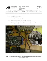
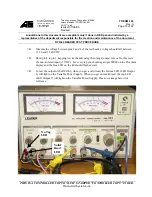
7.39.1 On the variable power supply, the cable from the fixed voltage section (+6VDC)
should be connected to the output port on the reader.
7.39.2 LED Output 2 – yellow wire to anode LED, cathode of LED to negative side of +6V
output (variable voltage output section).
7.39.3 LED Output 1 – blue wire to anode LED, cathode of LED to negative side of +6V
output (variable voltage output section).
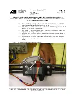
7.39.4 Meter is set on +25V reference with voltage set at 5VDC using reference knob to
adjust.
7.39.5 +6V output is set to 5VDC using voltage adjust knob on +6VDC side of power
supply. To check level push Meter button to +6V read bottom scale of voltage
display.
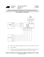
7.40
Plug the test cable trigger input into trigger #2.
Pin 1