background image

Hardware and physical integration guideline PCR Sensor A111


Page 20 of 32 


© 2022 by Acconeer 

– All rights reserved 


2022-03-08 


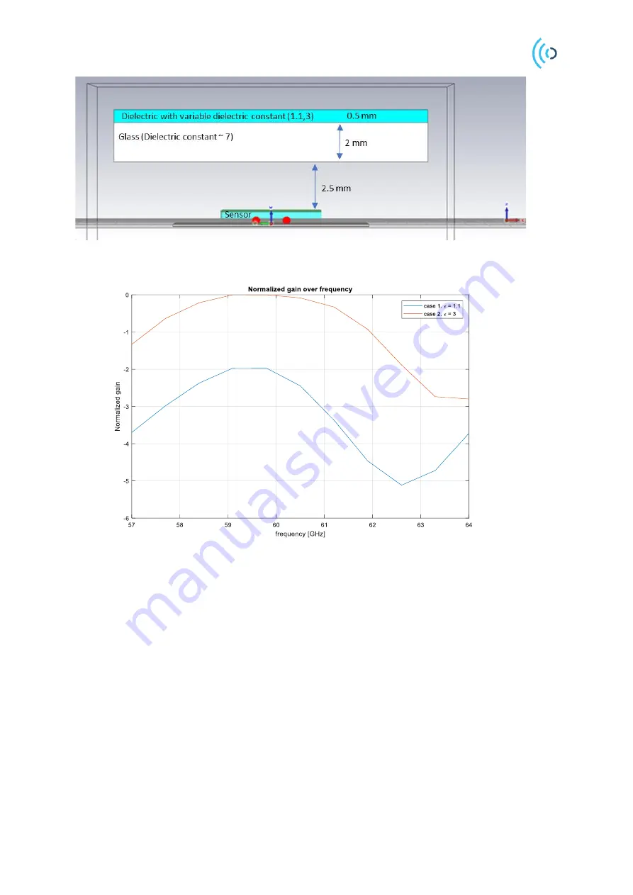
Figure 20. Simulation scenario: Sensor, air-gap, the matching layer and the screen. 


Figure 21. Normalized antenna gain (Tx or Rx antenna gain) where the matching layer dielectric constant is set to 1.1 
and 3. 

Summary of Contents for A111

Page 1: ...Hardware and physical integration guideline PCR Sensor A111 User Guide...

Page 2: ...integration guideline PCR Sensor A111 Page 2 of 32 2022 by Acconeer All rights reserved 2022 03 08 Hardware and physical integration guideline PCR Sensor A111 User Guide Author Acconeer Version 1 5 2...

Page 3: ...t 8 3 1 Sensor ground plane size 8 3 2 Impact of PCB routing and nearby components 8 3 3 Impact of conformal coating 10 3 4 Sensor underfill 11 4 Physical Integration 12 4 1 Radome integration 12 4 2...

Page 4: ...pectively 1 1 Radar loop equation Consider a signal transmitted through free space to a radar target located at distance R from the radar Assume there are no obstructions between the radar and the rad...

Page 5: ...field distance from the sensor 1 m The far field distance can be determined by the aperture of the sensor and the radar target farfield 2 2 2 where A is the largest dimension of either the sensor or t...

Page 6: ...low leakage power switch in between the two 1 8 V domains In both cases a control signal PMU_ENABLE is needed See Figure 3 for details Figure 3 Block diagram of how to connect a Power Management Unit...

Page 7: ...All rights reserved Figure 4 An example of how to connect a power switch to reduce the leakage current when A111 is powered off 2 2 SPI Interface To optimize signal integrity of the SPI bus it is rec...

Page 8: ...5 Simulated relative radar loop gain as a function of ground plane side length x Ground plane is a solid square ground plane without routing In terms of regulatory compliance any openings in the groun...

Page 9: ...les in Figure 6 Omitting thermal reliefs as in Figure 6a can increase the boresight RLG by approximately 2 dB provided there are no other interfering components or PCB traces close to the sensor A sma...

Page 10: ...electrically longer 2 Reflection and refraction loss due to the interface between the sensor and the coating 3 Dielectric loss in the coating material This can usually be neglected for thin coating la...

Page 11: ...0 Simulated impact of conformal coating with r 2 and r 3 for different thicknesses 3 4 Sensor underfill Underfills can be used to fill the gap between the sensor package and PCB The sensor underfill m...

Page 12: ...he reflection coefficient has a low value Therefore a low dielectric constant material will minimize the reflections and reduce the impact on the radiation pattern and insertion loss Typically radomes...

Page 13: ...d power from the target versus the radome to sensor distance for two different service profiles Profile 2 MaxSNR and Profile 1 MaxDepth Amplitude is nomalized by the maximum value of Free Space Amplit...

Page 14: ...eff where is the thickness of the dielectric When the wave reaches the dielectric air interface 01 another transmission 10 01 and reflections 10 01 happens Notice that the wave will have a sign chang...

Page 15: ...a 180 phaseshift Figure 15 Impact of the thickness of the radome made of ABS on the reflected amplitude variation The amplitude is normalized to maximum value of the Free Space FS Profile set to Prof...

Page 16: ...ved 2022 03 08 The optimum distance is valid if the thickness of the radome is optimum as well Otherwise to have a minimum insertion loss on the received signal the distance to the sensor should follo...

Page 17: ...space Figure 16 Impact of the different materials on the radiation pattern H plane Amplitude is stated in one direction Tx or Rx side For Radar Loop Gain RLG the values will be doubled Figure 17 shows...

Page 18: ...be doubled It is not recommended to place the cover directly on the sensor Figure 18 shows the radiation pattern on the H plane when the cover ABS plastic sheet is located on top of the sensor In comp...

Page 19: ...ic constant is the matching layer Depending on the degree of the freedom one can find the optimum thickness or the optimum dielectric constant for the anti reflection layer Figure 19 Illustration of t...

Page 20: ...age 20 of 32 2022 by Acconeer All rights reserved 2022 03 08 Figure 20 Simulation scenario Sensor air gap the matching layer and the screen Figure 21 Normalized antenna gain Tx or Rx antenna gain wher...

Page 21: ...s and the second is based on the phase correcting plate which is called Fresnel Zone Plate FZP lens The shape of the hyperbolic lens is chosen so that the rays passing through the lens originating fro...

Page 22: ...lens with the radome with respect to the free space scenario for the XM112 module see Figure 23 for the prototype pictures The maximum gain happens at 7 5 mm distance for both lenses Other maxima hap...

Page 23: ...XM112 radome The amplitude is normalized to Free Space FS Gain is stated in one direction Tx or Rx side For Radar Loop Gain RLG the values will be doubled Figure 25 Gain variation of the HPL and FZP l...

Page 24: ...FZP lens the distance tolerance of 0 5 and 1 mm results in 0 5 and 1 dB gain loss respectively For radar loop HPBW and RLG refer to module datasheets and the lens user guide When the focal distance i...

Page 25: ...the sensor is set to 2 mm Radius is in dB scale normalized to free space maximum gain Gain value is stated in one direction Tx or Rx side For Radar Loop Gain RLG the values will be doubled Figure 28...

Page 26: ...ne direction Tx or Rx side For Radar Loop Gain RLG the values will be doubled 5 3 FZP Lens Design The FZP lens characterized in the previous chapters was made of ABS plastic If other materials are to...

Page 27: ...step s is the thickness of each step F is the focal point p is the number of steps is the wavelength in free space 5 mm at 60 GHz and is the dielectric constant of the chosen material at 60 GHz By us...

Page 28: ...Hardware and physical integration guideline PCR Sensor A111 Page 28 of 32 2022 by Acconeer All rights reserved 2022 03 08 For further details regarding FZP and hyperbolic lens design see 2...

Page 29: ...ical integration guideline PCR Sensor A111 Page 29 of 32 2022 03 08 2022 by Acconeer All rights reserved 6 Appendix A Materials Table 1 Measured dielectric constant and loss tangent of different mater...

Page 30: ...ey IEEE Press 2013 3 S R Artem Boriskin Aperture Antennas for Millimeter and Sub Millimeter Wave Applications Springer 2017 4 Acconeer Expolration Tool Online Available https acconeer python explorati...

Page 31: ...by Acconeer All rights reserved 8 Revision Date Version Changes 2019 11 13 1 0 Original version 2020 07 02 1 2 Comments on the gain values 2020 11 25 1 3 Added information about conformal coating Upd...

Page 32: ...particular industry standard Acconeer is not responsible for any failure to meet such industry standard requirements Unless explicitly stated herein this document Acconeer has not performed any regul...

Reviews: