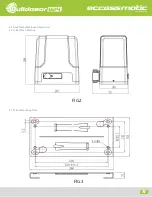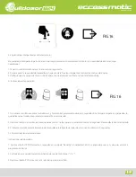
FIG.12
Opening your life
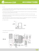
1. Power supply port (P7) (Transformer Output)
Transformer specification: 120VAC/22VAC Rated power: 120W
2. Battery and solar panel ports (P5)
Battery specification: 12V/9AH Solar charge controller: 24V
3. Direction sensor port (P3)
4. Motor port (P8)
5. Hall sensor port (P6)
6. Alarm lamp and infrared sensor ports (P4)
Alarm lamp type: LED Voltage: 12/24VDC Infrared sensor: NC
7. External button and antenna ports (P1)
External button: NO
5.2 Operation Interface Instruction
Indicator Lights:
L0 (Green): Indicating the control board working status and menu status.
L1-L5 (Red): Indicating the settings, parameters and errors.
Setup Buttons
PROG: Enter into or exit the setting menu.
- and +: Functions selection and parameter adjustment.
SET: Travel Limit Position Setting, Enter into the selection, save the setting.
5.3 Travel Limit Position Setting
Note:
The travel limit position must be settled according to the gate travel length after the first installation
of the gate opener.
5.3.1 Operation Instruction for Travel Limit Position Setting:
A. Operation Instruction
1. Enter into Setting Mode:
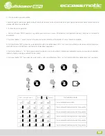
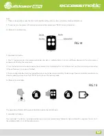
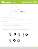
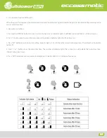
a.Press “SET” for 3sec to confirm to reset the travel limit position. The indicator lights will be on in sequence from L5 to L1.
FIG.11
824
10


