Manual PCI-A12-16A
29
Programming Examples
Generating a Square Wave Output
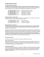
To program Counters #1 and #2 for a 1 KHz output you need to divide the 1MHz crystal oscillator input by
1,000. To obtain a symmetrical waveform, the divisor loaded into the counter should be an even number. If it
is an odd number, then one half of the waveform would be one input clock pulse period longer than the other.
A convenient divisor to use in counter #1 is 10 and counter #2 is 100 (because 10 x 100 = 1,000).
outportb(BASEA B, 0x76);
/* counter #1 to square wave mode */
outportb(BASEA B, 0xb6);
/* counter #2 to square wave mode */
outportb(BASEA 9,10);
/* write lower byte, counter #1 */
outportb(BASEA 9,0);
/* write upper byte, counter #1 */
outportb(BASEA A,100);
/* write lower byte, counter #2 */
outportb(BASEA A,0);
/* write upper byte, counter #2 */
Using Counter #0 as a Pulse Counter
Since the counters are "down" counters the resulting count is subtracted from the starting value to determine
the number of pulses. This example starts with a value of 65,535:
outportb(BASEA B,0x30);
/* counter #0, mode 0 */
outportb(BASEA 8,0xff);
/* counter #0 low load byte */
outportb(BASEA 8,0xff);
/* counter #0 high load byte */
Measuring Frequency and Period
The two previous sections show how to count pulses and generate output frequencies. It is also possible to
measure frequency by raising the gate input of Counter 0 for a known time interval and counting the number
of clock pulses accumulated for that interval. The gating signal can be derived from Counters #1 and #2
operating in a square wave mode.
Counter #0 can also be used to measure pulse width or half period of a periodic signal. The signal should be
applied to the gate input of Counter #0 and a known frequency (such as the 1MHz crystal controlled oscillator)
applied to the Counter #0 clock input. During the interval when the gate input is low, Counter #0 is loaded with
a full count of 65,535. When the gate input goes high, the counter begins decrementing until the gate input
goes back low at the end of the pulse. The counter is then read and the change in count is a linear function of
the duration of the gate input signal. Longer pulse durations can be measured if Counters #1 and #2 are used
as the input clock source for Counter #0, or by using an external clock source.
Generating Time Delays
There are four methods of using Counter #0 to generate programmable time delays.
Pulse on Terminal Count
After loading, the counter output goes low. Counting is enabled when the gate goes high. The counter output
will remain low until the count reaches zero, at which time the counter output goes high. The output will
remain high until the counter is reloaded by a programmed command. If the gate goes low during countdown,
counting will be disabled as long as the gate input is low.
Programmable One-Shot
The counter need only be loaded once. The time delay is initiated when the gate input goes high. At this point
the counter output goes low. If the gate input goes low, counting continues but a new cycle will be initiated if
the gate input goes high again before the timeout delay has expired; i.e., is re-triggerable. At the end of the
timeout, the counter reaches zero and the counter output goes high. That output will remain high until re-
triggered by the gate input.


