background image

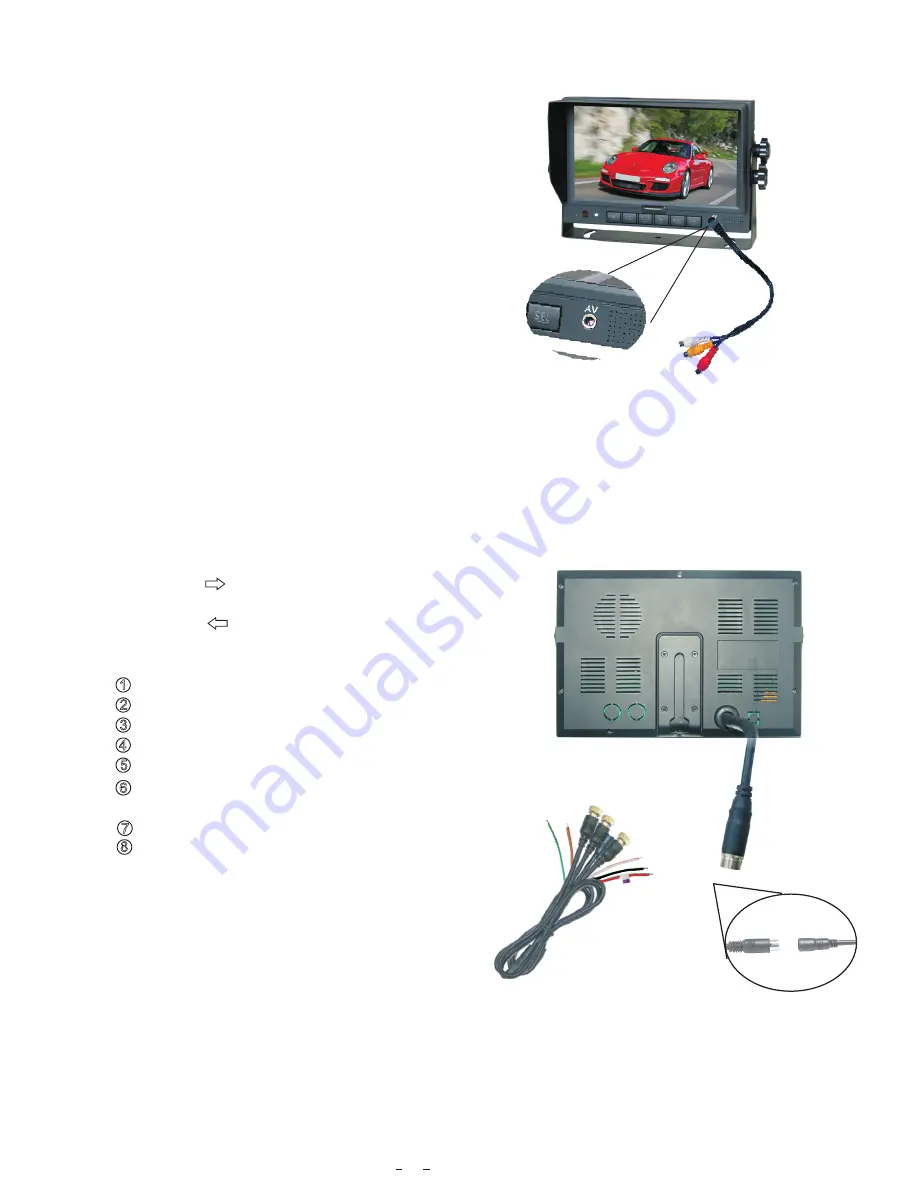
7.1. Connection of AV Input Cable

Align the small end of AV conversion adapter with the 

AV jack on the front panel of the display.  Then plug 

in.  Connect the RCA connectors to the output signal of 

the video and/or audio of the DVD/ VCD player. 

8

7.  Basic Operation 

7.2. Connection of AV Adapter and Controller Cable  

5

Audio/ Video Input

Brightness increase Brightness decrease Channel selection -

AV1/AV2/AV3/AV Selector

Menu

Remote control

sensor

Light level sensor

Power switch

Power indicator

Digital

 Color 

5.  Parts Identification

Hold the cable , align the side of jack 

marked with      on the female 13-pin 

connector  with the male 13-pin connector 

marked with        then firmly plug together.

    Black 4 pin male  for Camera1.     

       Black 4 pin male for Camera 2.     

    Black 4 pin male for Camera 3.    

       Single red wire to power wire of DC / 10-32V.

       Single black wire to GND.

       Single brown wire to positive power wire of the

        back-up light. 

    Single white wire to positive power wire of  left Light . 

       Single blue  wire to positive power wire of  right light .

1

2
3

4

5

6

7

8

Loudspeaker

Mounting bracket installation

LCD screen

Summary of Contents for LCDRV700

Page 1: ...Digital LCD Color Monitor Operating Instructions Please read this manual thoroughly before operating the unit and keep it for future reference V1 0 LCDRV700...

Page 2: ...ures 4 Accessories 5 Parts Identification 6 Remote Control Operation 7 Basic Operation 8 Menu 1 Picture 2 Option 3 System 9 Troubleshooting Contents 14 3 Technical Specifications 13 12 10 8 6 5 10 4 3...

Page 3: ...or is not designed to be waterproof 1 Operating Precautions 1 The device may be powered by a 12 or 24 volt automotive battery or vehicle electrical system 2 Observe polarity power s do not Make sure a...

Page 4: ...of sufficient magnitude to constitute risk of electric shock to persons This symbol is intended to alert the user to the presence of important operating and maintenance servicing instructions in the l...

Page 5: ...1 TFT LCD monitor with wide angle view and high resolution display 2 Picture image may be adjusted for Horizontal Vertical Mirror and Normal viewing 3 Select from 8 languages for user operation 4 Auto...

Page 6: ...ferent for different application Special Notice 4 U Support Bracket Center Mount Bracket adapter cable IR Remote control Flush Mount optional Detaching Piece Front Panel AV Input adapter Angle Adjustm...

Page 7: ...crease Brightness decrease Channel selection AV1 AV2 AV3 AV Selector Menu Remote control sensor Light level sensor Power switch Power indicator Digital Color 5 Parts Identification Loudspeaker Mountin...

Page 8: ...Picture Mode Language Selection Horizontal Flip 1 Please align the remote control with the infrared receiving window on the monitor to operate 2 Never disassemble the remote control or allow it to dr...

Page 9: ...different picture modes PERSONAL STANDARD SOFT VIVID LIGHT POWER Power Switch Press to turn on off the monitor Press to turn picture vertically Vertical Turning of Picture TIMER Press to set the timer...

Page 10: ...Cable Hold the cable align the side of jack marked with on the female 13 pin connector with the male 13 pin connector marked with then firmly plug together Black 4 pin male for Camera1 Black 4 pin ma...

Page 11: ...ve power supply of DC 10 32V Single black wire to GND Single brown wire to positive power wire of back up light Single white wire to positive power wire of left turn light Single blue wire to positive...

Page 12: ...reen as illustrated below Press CH to select BRIGHT PICTURE BRIGHT CONTRAST COLOR VOLUME 50 50 50 50 Press to adjust the brightness level 7 4 3 When the brown wire is connected to the positive wire of...

Page 13: ...on this menu will not display Press CH to select SCALE ADJUST PICTURE BRIGHT CONTRAST COLOR VOLUME AUTO DIM SCALE ADJUST 40 45 40 50 OFF Press to select or The scale can be adjusted when it is display...

Page 14: ...ENGLISH Press to select ON OFF Scale refers to the reversing distance indicator displayed on the monitor Press CH to select SCALE LANG SCALE CAM1 CAM2 CAM3 AV options display on the screen as illustr...

Page 15: ...CK HORIZONTAL VERTICAL ZOOM COLOR SYS AUTO ON 16 9 Press to select ON OFF 3 System COLOR SYS BLUE BACK HORIZONTAL VERTICAL ZOOM functions will display on the screen as illustrated below Press CH to se...

Page 16: ...ly Check whether the environments temperature is too low Adjust the color settings The black wire of the monitor AV cable to the reversing light may be loose The red wire from the monitor may be loose...

Reviews: