background image

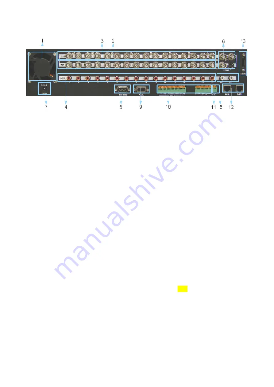
2.2 Rear Panel

1. FAN

System fan

2. 16ch video inputs

16 channel composite video inputs with BNC connectors . NTSC or PAL video sources
can be connected in DVR. But NTSC and PAL video sources for 16ch video inputs can
not be mixed. If they are mixed, DVR can’ not be operated properly.

3. 16ch loop through outputs

16 channel composite video outputs with BNC connectors. If the connection of
loopthrough video outputs into another video equipments is requested, 16ch
loopthrough outputs can be utilized for it.

4. 

16ch audio input (RCA)

Connect the audio source to audio input

.

5. 2ch Audio Output (RCA)

Audio output to your amplifier.

6. 3ch composite video output and 1 S-Video output

Two video output (MON1 and MON2) and one S-Video are same video output, used to
monitor live, playback pictures. The other is used to monitor SPOT output which
displays all of connected video channels sequentially.

7. Power Input (from Adapter)

Connect the adapter to the DVR for DC power supply. (DC 19V).

8. VGA Output

VGA output can be connected to LCD monitor or CRT monitor.

9. RS232 (It can be utilized for future option.)

10. Alarm input and relay output 16 alarm inputs and 4 relay output with NO, NC

To make secure connections on the Alarm Connector Strip, press and hold the button

10

Summary of Contents for ADR-7616

Page 1: ...User Manual Version 1 3 8CH 16CH H 264 Standalone DVR ADR 7616...

Page 2: ......

Page 3: ...ment on the part of vendor who assumes no liability or responsibility for any errors that may appear in this manual This manual contains materials protected under International Copyright Laws All righ...

Page 4: ...n4 Menu Setup 18 4 1 TIME 19 4 2 RECORD 21 4 3 SCHEDULE 23 4 4 MOTION 24 4 5 ALARM 25 4 6 NETWORK 28 4 7 ADVANCED 31 Section5 Live Display 41 Section6 Backup 45 Section7 PTZ Control 45 Section8 F W Up...

Page 5: ...simultaneously This high quality DVR is absolutely the best choice for your security surveillance 1 2 Product Features H 264 compression format 120fps at D1 for recording 16ch all real time recording...

Page 6: ...MS Option Other PTZ Pelco D Pelco P protocol Power DC 19V 96W Dimension 430 W x 88 H x 340 D mm 1 4 Package Digital Video Recorder 1 Power Adapter Power Cord 1 Screw Bag 1 Black screws are used for sc...

Page 7: ...l turn ON during data backup or F W upgrade through USB drive e LOCK This red LED will turn ON while LOCK button is working f Remote Controller receiver Remote controller sensor input window 4 Channel...

Page 8: ...g Search button This can be used to find out proper recorded file for playback or backup Searching menu can be displayed by pressing this button h REW This button can be used for high speed backward p...

Page 9: ...power When this button is pressed password is requested When right password is input DVR power will be turned off 8 USB 2 0 connector Used for F W upgrade and data backup 9 CF slot inserting CF card...

Page 10: ...A Connect the audio source to audio input 5 2ch Audio Output RCA Audio output to your amplifier 6 3ch composite video output and 1 S Video output Two video output MON1 and MON2 and one S Video are sam...

Page 11: ...ctor 3 4 Relay output 4 relay output with NO or NC can be sent to external device You can select NO or NC according to characteristic of mechanical or electrical switch 11 RS485 PTZ cameras can be con...

Page 12: ...d by the red circles Remove the screws and keep them in a safe place for latter use Once the upper casing is removed the internal layout can be seen The DVD RW rack is on the left side while the HDD r...

Page 13: ...e HDDs are installed into the HDD racks place the racks back align them with the holes on the chassis and tighten the screws 4 Finally connect the SATA and SATA power cable to the back of the HDDs Ins...

Page 14: ...two screws on the DVD RW rack and split it as the two part shown as below 3 Position the two mounting plates on either side of the DVD RW and then tighten them with screws 4 Now place the assembly in...

Page 15: ...5 Finally connect the SATA and SATA power cable to the back of the DVD RW DVD RW Installation is now completed 15...

Page 16: ...ers setup 3 SCHEDULE Weekly recording schedule setup for Schedule recording mode 4 MOTION Motion Area Sensitivity setup for Motion recording mode 5 ALARM Alarm input type selection and Buzzer setup 6...

Page 17: ...3 SCHEDULE 4 MOTION 4 1 MOTION CH 4 1 SENSITIVITY 4 3 DETECTION AREA 5 ALARM 5 1 ALARM INPUT 5 2 ALARM OUTPUT 1 5 3 ALARM OUTPUT 2 5 4 BUZZER 5 4 1 KEY TONE 5 4 2 ALARM 5 5 EMAIL NOTIFICATION 6 NETWOR...

Page 18: ...AMERA TITLE DISPLAY 7 2 2 RECODE MODE DISPLAY 7 2 3 AUTO HIDE TOOLBAR 7 2 4 DWELL 7 2 5 DATE TIME POSITION 7 2 6 VGA MONITOR RATIO 7 2 7 RECORD DATE TIME 7 3 CAMERA 7 3 1 CAMERA 7 3 2 CAMERA TITLE 7 3...

Page 19: ...et as ON Default is OFF AdminLock can be set as ON or OFF in ADVANCED SYSTEM NOTE Default password is 111111 To access the DVR Menu press MENU To escape MENU ESC can be used Buttons for movement in Me...

Page 20: ...board Number characters can be selected and input by using direction and ENTER buttons After inputing the right date press SAVE ESC to save it Mouse input is also available 2 TIME Move Highlight icon...

Reviews: