background image


AbuseMarK


LCD


Adapter


Manual


12/17/2013


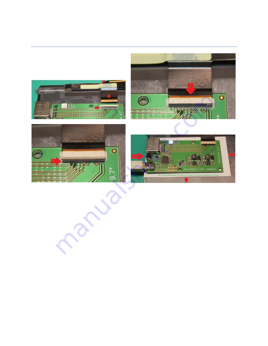
Connecting adapter to LCD Panel 


1.


Carefully


lift


up


lever


on


the


back


of


connector


2.


Align


FPC


cable


with


circuit


(gold)


side


facing


up,


and


push


it


into


connector


3.


Stop


when


cable


reaches


shown


position.


Do


not


force


cable


further


into


the


connector


4.


While


keeping


cable


aligned,


push


back


on


the


lever


to


lock


cable


inside


If


testing


with


the


board


on


the


back


of


LCD,


make


sure


to


place


paper


or


some


other


non

conductive


material


between.


Or


else,


the


board


will


short


circuit


with


the


aluminum


back


of


the


panel.


Summary of Contents for LCD

Page 1: ...yPort connector 2 51 pin FPC connector for LCD 3 USB connector for power or firmware update 4 Power button 5 Power Status LED 6 External 5V source see External Power section For functionality of Power button see the LCD Adapter firmware features and operation section last page ...

Page 2: ...and push it into connector 3 Stop when cable reaches shown position Do not force cable further into the connector 4 While keeping cable aligned push back on the lever to lock cable inside If testing with the board on the back of LCD make sure to place paper or some other non conductive material between Or else the board will short circuit with the aluminum back of the panel ...

Page 3: ...V source When arranging many panels in array its easier to source a single 5V connector for all panels and avoid USB cable mess A standard 2 54mm 0 1 pin header connection is provided for this purpose User can solder in pin header or wires directly Left side is positive and right side is negative The following 3 pads tx GND rx are NOT related to power and 5V must not be connected to them at any ti...

Page 4: ...e Upgrade procedure Remove power Unplug USB or disconnect external 5V and press and HOLD Power button while connecting USB cable Firmware update on external 5V power is NOT suported Status LED will light up RED and remain lit and new device will install ST Device in DFU mode Start DFuse Demo application In the Upgrade or verify box in the GUI make sure to uncheck Verify After download if checked C...

Page 5: ...connect from DisplayPort signals press the power button twice BLUE full power on RED standby Full power off LED off Since most common use case does not involve disconnecting from DisplayPort as this would cause other monitors to flicker while display adapter is reconfiguring if adapter is in standby mode for more than a few seconds pressing the power button returns to Full power mode turning on ba...

Reviews: