background image


[7] 

wAppLoxx Pro oval 

 installation instructions  


Operating the wAppLoxx Pro, reader outside  


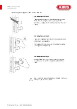
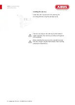
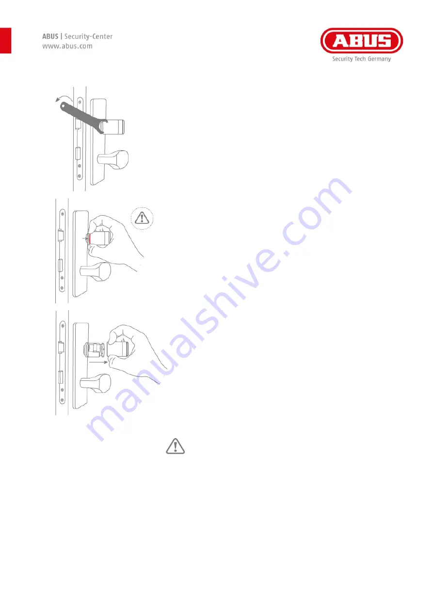
Removing the outer cap 1 

The outer cap (1) has to be removed in order to insert 
the battery (3). Using the opening key (a), fix the 
mounting plate (4) onto its notch and unscrew the outer 
cap (1). 


Removing the outer cap 2 

The sealing ring (marked red) of the knob is located just 
behind the mounting plate.  

Carefully pull the outer cap over the sealing ring using 
your fingers and stop briefly.  


Removing the outer cap 3 

Once you have pulled the outer cap over the sealing 
ring, the outer cap can be completely pulled off the 
knob.   


Make sure that you pull the knob out straight. If not, you 
risk ripping off the circuit board


Summary of Contents for wAppLoxx Pro Series

Page 1: ... 1 wAppLoxx Pro oval installation instructions Installation and operating instructions wAppLoxx Pro WLX Pro Access and Intrusion WLX Pro Oval WLX Pro Rokoko ...

Page 2: ...a 5 Installing the wAppLoxx Pro Cylinder 6 wAppLoxx Pro oval cylinder individual parts 6 Operating the wAppLoxx Pro reader outside 7 Operating the wAppLoxx Pro Rokoko 9 Logging the wAppLoxx Pro Cylinder into and out of the wAppLoxx Control 12 Operating the wAppLoxx Pro Cylinder 13 ...

Page 3: ...e right to make changes to this manual without prior notice ABUS Security Center hereby declares that the radio system type 505272 and all WLX Pro cylinders comply with RED Directive 2014 53 EU The full EU Declaration of Conformity text can be found at https www abus com ger Objektsicherheit Zutrittskontrolle wAppLoxxPro Safety information Explanation of symbols The triangular warning symbol indic...

Page 4: ...to very high temperatures Keep batteries away from children Batteries are not rechargeable Batteries must not be dismantled pierced or otherwise damaged They must not be burned come into contact with water or be short circuited When replacing the batteries the respective temperature specifications of the manufacturer must be observed To ensure a long lifespan and safe operation you must use the fo...

Page 5: ...yte Mifare Classic tags we accept no liability for the use of other tags Configuration Via wAppLoxx Pro Control Power supply 3 V CR2 lithium battery Conditions of use 25 C to 65 C Drilling protection Standard Security IP protection class IP 67 Outer knob dimensions Diameter 38 mm length 48 mm Material Knob stainless steel reading cap plastic Outer knob colour variants black white grey Delivery sta...

Page 6: ...he wAppLoxx Pro Cylinder wAppLoxx Pro oval cylinder individual parts 1 Outer cap 2 WLX Pro cylinder body oval 3 Battery 4 Mounting plate 5 Basket 6 PCB bracket 7 Electronic screws Tools required must be ordered separately a Outer cap opening key 1 2 3 a 4 5 6 7 ...

Page 7: ...and unscrew the outer cap 1 Removing the outer cap 2 The sealing ring marked red of the knob is located just behind the mounting plate Carefully pull the outer cap over the sealing ring using your fingers and stop briefly Removing the outer cap 3 Once you have pulled the outer cap over the sealing ring the outer cap can be completely pulled off the knob Make sure that you pull the knob out straigh...

Page 8: ...ve terminal facing antenna circuit board Installing the outer cap Screw the outer cap 1 back on by securing the mounting plate using the opening key e There is a marking on the outer cap that makes it easier to position the outer cap correctly on the groove of the knob When installing the outer cap it is essential to ensure that the orange O ring lies flush between the mounting plate and the knob ...

Page 9: ... the lock from the inside Firstly remove the outer cap 1 Removing the electronic knob 1 After removing the outer cap the electronic knob 5 6 must be removed After this remove the PCB bracket 6 from the basket 5 and remove the basket 5 from the shaft including the mounting plate 4 Installing the cylinder body Once the outer knob has been removed the cylinder body 2 can be mounted in the lock ...

Page 10: ... ensure that the cylinder is tight it must be ensured that sufficient screw glue is applied to the electronic screws Installing the PCB bracket Place the PCB bracket 6 in the basket 5 and secure using two small electronic screws When inserting the bracket ensure that the EMC contact is not bent see figure on the left Inserting the battery Make sure that the battery 3s is placed on the white batter...

Page 11: ...ecuring the mounting plate 4 using the opening key e There is a marking on the outer cap 1 that makes it easier to position the outer cap correctly on the groove of the knob 3 When installing the outer cap it is essential to ensure that the orange O ring lies flush between the mounting plate 4 and the knob 3 ...

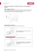
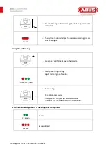
Page 12: ...ase see the user guide of the wAppLoxx Control Pro Now hold the wAppLoxx Pro System Card in front of the cylinder to be registered Logging a wAppLoxx Pro Cylinder out In order to log a cylinder out of the WLX Pro system proceed as follows Hold the wAppLoxx Pro System Card in front of the cylinder to be logged out 10 x red A flashing red signal will come on While this flashing red signal is on you ...

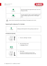
Page 13: ...turn to its original state Both cards are included in the scope of delivery of the wAppLoxx Pro Control Operating the wAppLoxx Pro Cylinder 1 green A brief green flash signals that the tag is being read and sent Unlocking opening locking 1 Present a valid tag to the reader 2 green 2 After presenting the tag 2 rapid green flashes 3 Remove tag The system is coupled for 6 or 12 seconds The door lock ...

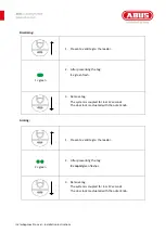
Page 14: ...the tag 1 green flash 3 Remove tag The system is coupled for 6 or 12 seconds The door lock is actuated with the outer knob Arming 1 Present a valid tag to the reader 2 green 2 After presenting the tag 2 rapid green flashes 3 Remove tag The system is coupled for 6 or 12 seconds The door lock is actuated with the outer knob ...

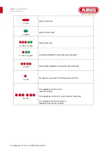
Page 15: ... process with a red light Using the fallback tag 1 Present a valid fallback tag to the reader 1 red 2 green 2 After presenting the tag rapid red and green flashing 3 Remove tag Repeat process twice The system is coupled for 6 or 12 seconds The door lock is actuated with the outer knob Possible acknowledgements of the wAppLoxx Pro Cylinder 2 green Access 3 x red Access denied ...

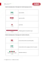
Page 16: ...d 2 green Authorised fallback transponder was presented 4 x red Unauthorised fallback transponder was presented 1 x red No wireless connection to the wAppLoxx Control 6 x red The wAppLoxx Control is not ready for arming The wAppLoxx Control Pro is not ready for disarming The wAppLoxx Control receives no feedback from the alarm panel ...

Page 17: ...essful 3 red Logout successful 1 x red Login failed 10 x red Fallback tag reset card required to log out Possible acknowledgements of the wAppLoxx Pro Cylinder initialisation 2 x red Communication with the outer knob possible 2 green Communication with the wAppLoxx Control Pro possible 1 x green 1 red 1 green 1 x red Initialisation of WLX Pro ...

Page 18: ...the end of its lifespan dispose of the product according to the applicable legal requirements Please contact your dealer or dispose of the products at the local collection point for electronic waste ABUS Security Center GmbH Co KG Linker Kreuthweg 5 86444 Affing If you have any technical questions please contact your specialist dealer ...

Reviews: