10
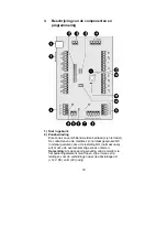
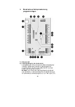
9.) Bus output
For connecting further extension modules to the bus.
10.) Not used
All dip-switches must be switched to “OFF”.
11.) Tamper jumper
If the jumper is closed, the lid tamper of the extension
module is switched off.
12.) Tamper contact
13.) Volume potentiometer
For adjusting the volume of external loudspeakers
14.) Connecting loudspeakers (optional)
Up to 2 external 16 Ohm loudspeakers can be connected in
series. The loudspeakers can be adjusted by the
potentiometer on the PCB.
Important:
If you connect an external loudspeaker, you
should connect an extra voltage supply to the 8-zone wired
extension.
Output (-2)
In the factory setting, the relay switches from 12 V DCto 0V
when the output is activated. The maximum current is
100mA. This output can be inverted during programming if
necessary.
15.) JP4
The jumper must be set to Position 3.
16.) Output (+1)
In the factory setting, the relay switches from 12 V DCto 0V
when the output is activated. The maximum current is
100mA. This output can be inverted during programming if
necessary.
17.) Address of 8-zone wired extension
Set the jumper to the position matching the extension.
Important:
Make sure that an address is not used more
than once on a bus.


