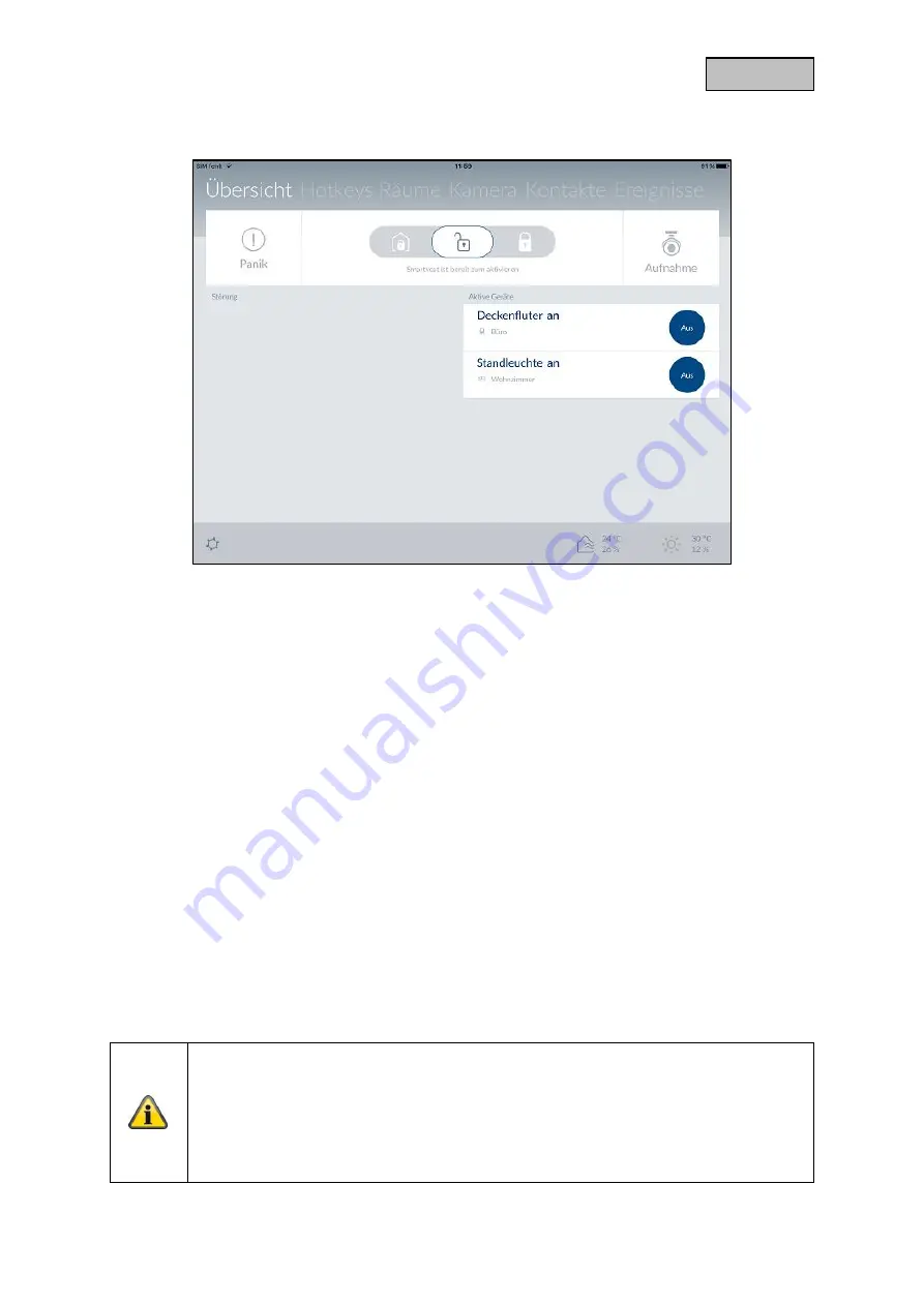
Abus Smartvest FUAA35000 User Manual Download Page 30


30 

Deutsch 

4.  Bedienung 


Die  Smartvest  App  ist  in  zwei  grundlegende  Menüführungen  unterteilt.  Die  Bedienung  und  die 
Konfiguration. 


In diesem Kapitel wird Ihnen die Bedienung der Smartvest durch die Smartvest App demonstriert. 

Zur Konfiguration der Smartvest beachten Sie bitte das Kapitel 5. 


Folgende Funktionen sind in der Bedienung verfügbar: 


Übersicht der wichtigsten Informationen und Funktionen 

o


Aktiv / Intern aktiv / Deaktiv schalten der Smartvest 

o


Aktive Geräte 

o


Störungen 


Übersicht und Aktivierung Ihrer Hotkeys 


Übersicht Ihrer Räume und des Status der Raum-Melder 


Übersicht und Liveansicht Ihrer Kameras 


Übersicht und anrufen Ihrer Kontakte 


Übersicht der vorgefallenen Ereignisse 


Hinweis 

Je  nach  verwendetem  Betriebssystem  und  Endgerät  kann  die  tatsächliche  Darstellung 
geringfügig  von  den  in  dieser  Anleitung  eingefügten  Screenshots  abweichen.  Die 
Übersicht  der  Menüs  wird  in  dieser  Anleitung  mit  der  Hilfe  von  Tablet-Screenshots 
dargestellt  während  die  Beschreibungen  der  einzelnen  Menüpunkte  mit  der  Hilfe  von 
Smartphone-Screenshots  dargestellt  werden.  Die  Bezeichnungen  der  Menüpunkte  und 
die Menüführung sind jedoch auf jedem Gerät identisch. 


Summary of Contents for Smartvest FUAA35000

Page 1: ...gsanleitung Wichtige Hinweise und FAQs zu diesem Produkt und weiteren Produkten finden Sie auf der Internetseite www abus com Version 1 2 Originalbedienungsanleitung in deutscher Sprache Für künftige Verwendung aufbewahren ...

Page 2: ...n der jeweiligen Inhaber Alle Rechte vorbehalten Bei Fragen wenden Sie sich an ihren Facherrichter oder Fachhandelspartner Haftungsausschluss Diese Bedienungsanleitung wurde mit größter Sorgfalt erstellt Sollten Ihnen dennoch Auslassungen oder Ungenauigkeiten auffallen so teilen Sie uns dies bitte schriftlich unter oben angegebenen Adresse mit Die ABUS Security Center GmbH übernimmt keinerlei Haft...

Page 3: ...d bis zu 4 IP Kameras mit der kostenlosen App Die kostenlose App ermöglicht den weltweiten Zugriff auf die Zentrale Im Falle eines Alarms verfügt die Zentrale über eine integrierte lautstarke 90dB Sirene und kann parallel mit Push Benachrichtigungen via App und E Mail alarmieren Wichtige Sicherheitshinweise Allgemein Vor der ersten Verwendung des Gerätes lesen Sie bitte die folgenden Anweisungen g...

Page 4: ... einen Kurzschluss oder elektrischen Schlag verursachen kann Stellen Sie weder das Gerät Möbelstücke oder andere schwere Gegenstände auf die Kabel und achten Sie darauf dass diese nicht geknickt werden insbesondere am Stecker und an den Anschlussbuchsen Machen Sie niemals einen Knoten in ein Kabel und binden Sie es nicht mit anderen Kabeln zusammen Alle Kabel sollten so gelegt werden dass niemand ...

Page 5: ...onst Luftfeuchtigkeit kondensieren und zu elektrischen Kurzschlüssen führen kann Achten Sie bei allen Komponenten die für den Innenbereich und Außenbereich geeignet sind darauf dass die Komponenten keinen übermäßigen Erschütterungen und Vibrationen ausgesetzt sind die Komponenten nicht in unmittelbarer Nähe von Magnetfeldern z B Lautsprechern stehen der Kontakt mit aggressiven Flüssigkeiten vermie...

Page 6: ...n werden können Wartung und Pflege Wartungsarbeiten sind erforderlich wenn das Gerät beschädigt wurde z B wenn Netzstecker Netzkabel oder Gehäuse beschädigt sind Flüssigkeit oder Gegenstände ins Innere des Gerätes gelangt sind es Regen oder Feuchtigkeit ausgesetzt wurde oder wenn es nicht einwandfrei funktioniert oder heruntergefallen ist Wartung Falls Sie Rauchentwicklung ungewöhnliche Geräusche ...

Page 7: ...Komponenten 19 Allgemeine Einstellungen 21 3 Montage 23 FUAA35000 Smartvest 23 FUHA35000 Funk Steckdose 24 FUMK35000 Öffnungsmelder 24 FUBW35000 Bewegungsmelder 26 FURM35000 Rauch Hitze Warnmelder 27 FUSG35000 Sirene 28 FUBE35000 Fernbedienung 29 4 Bedienung 30 Navigationsleiste und Fußzeile 31 Übersicht 32 Hotkeys 34 Räume 35 Kameras 37 Kontakte 39 Ereignisse 40 Alarmansicht 41 5 Konfiguration 42...

Page 8: ...atus LED Aus System ist deaktiv Gelb An System ist deaktiv und es liegt eine Störung vor z B Batterie leer oder Öffnungsmelder ist offen Blau An System ist aktiv Rot An System ist aktiv und im Alarmzustand normaler Alarm Sabotagealarm oder Panik Alarm Netzwerk LED Grün An Verbindung zu Netzwerk und Internet Aus Verbindung zu Netzwerk ohne Internet Rot Blinkend Keine Netzwerkverbindung Optionaler S...

Page 9: ...ungen d h alle Einstellungen werden zurückgesetzt und das Pairing der Komponenten gelöscht Drücken Sie den Reset Knopf im spannungslosen Zustand der Zentrale und halten diesen 10 Sekunden gedrückt während Sie die Zentrale mit Spannung versorgen Die Power LED erlischt und ein durchgehender Ton ertönt Die Anlage startet anschließend neu RJ45 Anschluss Integrierter Netzwerkanschluss 10 100 Mbit Spann...

Page 10: ...e Richtung Schließen Sie anschließend das Batteriefach mit der Abdeckung Aufhängung Aufhängung für Wandmontage Bohrlochabstand 10 cm Bohrschablone liegt bei Lautsprecher Lautsprecher der Smartvest mit maximal 90db Lautstärke Hintergrund LED s Aus Aus System ist deaktiv Gelb An System ist deaktiv und es liegt eine Störung vor z B Batterie leer Öffnungsmelder ist offen Blau An System ist aktiv Rot A...

Page 11: ...ern Deutschland Österreich Schweden Niederlande Repeater Modus Die Funk Steckdose kann neben dem Schalten eines Verbrauchers zusätzlich als Funk Repeater für eine andere Komponente dienen Hierzu folgen Sie folgenden Schritten 1 Halten Sie die Taste 5 Sekunden gedrückt um den Repeater Modus zu aktivieren Die Status LED beginnt orange zu blinken 2 Führen Sie bei der Komponente die Sie mit der Funk S...

Page 12: ...sversorgung bis zu 1 Jahr Batterielebensdauer Die Smartvest App warnt Sie bei niedriger Batterie Folgen Sie den Anweisungen in der App Batteriewechsel Schieben Sie die Abdeckung des Batteriefachs nach unten heraus Ziehen Sie die leere 3V Knopfbatterie aus der vorgesehenen Halterung und legen eine neue 3V Knopfbatterie ein Schließen Sie das Batteriefach mit der Abdeckung nun wieder Magnet Komponent...

Page 13: ...gsmelders ein und entfernen Sie die Rückseite des Bewegungsmelders Entfernen Sie die leeren 3 AA 1 5 V Batterien aus der Kammer und legen Sie neue 3 AA 1 5 V Batterien ein Achten Sie dabei auf die im Boden beschriebene Richtung Bringen Sie den Bewegungsmelder an die montierte Rückseite wieder an Hinweis Im Testmodus wird der Energiesparmodus des Bewegungsmelders deaktiviert und löst somit bei jede...

Page 14: ... beiden Schrauben der Abdeckung Sie müssen die Schrauben nicht komplett entfernen Klappen Sie die Abdeckung auf der unteren Seite nach oben und führen Sie die Abdeckung anschließend heraus Sie können für eine bessere Erreichbarkeit der Schrauben die Gummiabdeckung des Sabotage Kontakts während dem Batteriewechsel kurzzeitig entfernen Entfernen Sie die leeren 4 C 1 5 V Batterien aus der Kammer und ...

Page 15: ...rgung bis zu 2 Jahre Batterielebensdauer Die Smartvest App warnt Sie bei niedriger Batterie Folgen Sie den Anweisungen in der App Batteriewechsel Ziehen Sie das Batteriefach an der Seite der Fernbedienung heraus Ziehen Sie die leere 3V Knopfbatterie aus der vorgesehenen Halterung und legen eine neue 3V Knopfbatterie ein Schieben Sie das Batteriefach wieder in die Fernbedienung Hinweis Die genaue R...

Page 16: ...artvest Installieren Sie die Smartvest App Hinweis Bitte beachten Sie dass die Smartvest App folgende Betriebssysteme als Mindestvoraussetzung voraussetzt Apple iOS 7 Android 4 0 Einrichtung der Smartvest Schließen Sie zuerst das beiliegende LAN Kabel an der Unterseite der Smartvest an und verbinden Sie dieses mit Ihrem Router Schließen Sie im Anschluss das beiliegende Netzteil an Hinweis Stellen ...

Page 17: ...anuell ein Alle kommenden Eingaben müssen dann ebenso manuell durchgeführt werden Gerätesicherheitscode Der Standard Gerätesicherheitscode 123456 ist bereits hinterlegt Bei der Ersteinrichtung drücken Sie auf Weiter Wurde der Gerätesicherheitscode bereits geändert geben Sie hier den korrekten Code an Standard Gerätesicherheitscode 123456 Beim ersten Log In werden Sie aufgefordert den Gerätesicherh...

Page 18: ...auf Speichern Sie haben nun Ihre Smartvest in die App eingebunden Gerätesicherheitscode bei erster Inbetriebnahme ändern Bei der ersten Inbetriebnahme oder nach Rücksetzung der Zentrale auf Werkseinstellungen werden Sie aufgefordert den Gerätesicherheitscode zu ändern Dieser muss mindestens 6 und kann maximal 16 Zeichen lang sein Folgende Zeichen sind zulässig Buchstaben a z A Z Zahlen 0 9 Sonderz...

Page 19: ...artvest zu gelangen Geben Sie das Passwort für die Einstellung Standard 123456 ein um alle Einstellungsmöglichkeiten zu öffnen Standard Passwort für Einstellungen 123456 Sie können dies in den erweiterten Einstellungen Sicherheitseinstellungen anpassen Komponente auswählen Wählen Sie in der Liste ganz oben Komponenten aus Drücken Sie oben rechts auf das Plussymbol zum Hinzufügen einer Komponente W...

Page 20: ...en finden Sie unter dem Kapitel 5 1 Komponenten Die Einstellungen Ihrer Komponenten finden Sie ebenso in dem Kapitel 5 1 Komponenten Wiederholen Sie diese Schritte für all Ihre Komponenten Hinweis Grundsätzlich senden alle Komponenten das Einlernsignal sobald diese mit Spannung versorgt werden Hinweis Zur Einbindung der kompatiblen Kameras für die Smartvest folgen Sie bitte zuerst der jeweiligen A...

Page 21: ...n Sie der App eine neue Smartvest hinzu oder wählen Sie Ihre Smartvest aus um die allgemeinen Einstellungen der Smartvest zu öffnen Smartvest Details Falls der Gerätesicherheitscode geändert oder falsch eingegeben wurde können Sie diesen hier für die Verbindung zur Smartvest anpassen Hinweis Wie Sie Ihren Gerätesicherheitscode ändern wird im Kapitel 5 Konfiguration beschrieben Aktivieren Sie das a...

Page 22: ...gerät abgefragt Sollten Sie Ihren App PIN vergessen haben deinstallieren Sie Ihre Smartvest App und installieren Sie diese neu Standard App PIN 123456 Deaktivieren Sie das automatische Einloggen für den App PIN damit bei jedem Start der App der App PIN abgefragt wird Nutzen Sie dies um den Zugriff auf die App zu verhindern falls andere Personen Ihr Endgerät benutzen Anleitung Hier können Sie die S...

Page 23: ...gnet FUAA35000 Smartvest Die Smartvest ist nur für den Innenbereich geeignet Beachten Sie hierzu die Hinweise bezüglich Aufstellort und Betriebsumgebung bei den Sicherheitshinweisen Allgemeine Montagehinweise Stellen Sie vor der Montage die Notstromversorgung über Batterie Ihrer Smartvest sicher 1 Öffnen Sie hierzu die Abdeckung des Batteriefachs durch das Drücken beider Klammern 2 Ziehen Sie den ...

Page 24: ...e Sender Komponente auf den Fenster oder Türrahmen Montieren Sie den Öffnungsmelder so dass die zwei Komponenten horizontal maximal 0 5 cm und vertikal maximal 1 5 cm voneinander entfernt sind Testen Sie im Zweifelsfall ob der Höhenunterschied bei Ihrem Fenster oder Ihrer Tür zu hoch ist indem Sie die beiden Komponenten an die gewünschte Position des Fensters oder der Tür aneinanderhalten und ansc...

Page 25: ...e die kleinere Magnet Komponente des Öffnungsmelders mit einem dünnen Schlitz Schraubendreher 2 Entfernen Sie die Abdeckung des Batteriefachs der größeren Sender Komponente des Öffnungsmelders 3 Schrauben Sie die kleinere Magnet Komponente auf die gewünschte Position des Fensters mit Hilfe von 2 Schrauben Zuvor sollten die vorgesehenen Löcher mit einem Schraubendreher oder Bohrer durchbrochen werd...

Page 26: ...von großen Metallstrukturen nahe an Netzleitungen oder Gasleitungen nahe elektronischer Geräte oder Funkgeräten oder näher als 30mm von der Decke entfernt montieren Der Erfassungsbereich des Melders ist nach unten gerichtet Neigen Sie deshalb den Melder nicht zu stark nach unten da ansonsten die Reichweite minimiert wird Empfohlen wird eine horizontale aufrechte Position Klebemontage 1 Für eine Wa...

Page 27: ...ieder auf die Halterung Bohrmontage ohne Halterung 1 Drücken Sie den Knopf an der Unterseite des Bewegungsmelders ein und entfernen Sie die Rückseite des Bewegungsmelders 2 Verwenden Sie die vorgesehen Löcher auf der Innenseite der Rückseite als Bohrvorlage für die Wand oder Eckenmontage 3 Bohren Sie die Löcher und setzen Sie die beiliegenden Dübel ein Schrauben Sie anschließend die Rückseite des ...

Page 28: ...ns 3 m ein um körperliche Schäden z B Gehör zu vermeiden Die Sirene ist nur für den geschützten Außenbereich geeignet IP44 Achten Sie darauf dass die Sirene außerhalb des Handbereichs mindestens 3m Montagehöhe angebracht wird Wählen Sie den Installationsort so dass die Sirene schon aus großer Entfernung gut sicht und hörbar ist Die Sirene wird durch erstmaliges Drücken des Sabotagekontakts aktivie...

Page 29: ...ernbedienung ist nur für den Innenbereich geeignet Beachten Sie hierzu die Hinweise Betriebsumgebung in den Sicherheitshinweisen Montage Verwenden Sie den Schlüsselring um die Fernbedienung an Ihren Schlüsselbund oder ähnlichem zu befestigen ...

Page 30: ... Übersicht und Aktivierung Ihrer Hotkeys Übersicht Ihrer Räume und des Status der Raum Melder Übersicht und Liveansicht Ihrer Kameras Übersicht und anrufen Ihrer Kontakte Übersicht der vorgefallenen Ereignisse Hinweis Je nach verwendetem Betriebssystem und Endgerät kann die tatsächliche Darstellung geringfügig von den in dieser Anleitung eingefügten Screenshots abweichen Die Übersicht der Menüs wi...

Page 31: ... in der Navigationsleiste farblich angezeigt Grau System ist deaktiv Gelb System ist deaktiv und es liegt eine Störung vor z B Batterie leer Blau System ist aktiv Rot System ist aktiv und im Alarmzustand z B Öffnungsmelder geöffnet Panik oder Sabotage Fußzeile Einstellungen In der unteren Fußzeile befindet sich unten links das Einstellungssymbol Drücken Sie auf dieses um in die Einstellungen der S...

Page 32: ...ins Bett gehen Smartvest ist deaktiviert bereit zum aktivieren In diesem Status ist das System nicht scharf geschalten Die Meldungen der meisten Sensoren lösen keinen Alarm aus Die einzige Ausnahme ist der Rauchwarnmelder der zu Ihrer Sicherheit unabhängig vom Systemstatus immer Alarm auslöst Außerdem wird Alarm ausgelöst wenn eine der Komponenten eine Sabotagemeldung sendet Empfohlene Anwendung S...

Page 33: ...ür die vorkonfigurierten Hotkeys Standard Werte gesetzt Falls Sie die Einstellungen für den jeweiligen Hotkey ändern möchten finden Sie die Einstellungen unter dem Punkt 5 3 Hotkeys Störung Falls Störungen z B Batterie leer vorliegen werden diese unter den Hotkeys angezeigt Werden die Störungen beseitigt verschwinden die Störungen aus der Übersicht Sie finden die Störungsmeldungen außerdem in der ...

Page 34: ...e Hotkeys Panik und Kamera sind bereits bei Erstinstallation hinterlegt Sie können in den Einstellungen siehe Kapitel 5 3 Hotkeys 9 weitere Hotkeys der Übersicht hinzufügen oder die bereits vorhandenen Hotkeys bearbeiten Drücken Sie auf den gewünschten Hotkey um diesen auszuführen Vorkonfigurierte Hotkeys Es befinden sich zwei vorkonfigurierte Hotkeys Panik und Kamera in der Hotkeyübersicht Diese ...

Page 35: ... Hotkey Räume Raumübersicht In der Raumübersicht befinden sich alle Räume denen mindestens eine Komponente hinzugefügt worden ist Unter dem Raumnamen werden jeweils maximal 2 Komponenten aufgelistet Raumdetails Drücken Sie auf den gewünschten Raum um die einzelne Raumübersicht zu öffnen Es werden alle Komponenten aufgeführt die diesem Raum hinzugefügt worden sind Verlassen Sie die einzelne Raumübe...

Page 36: ...36 Deutsch Farbcode Falls eine Störung einer einzelnen Komponente vorliegt wird der entsprechende Raum in der Raumübersicht und die Komponente gelb markiert ...

Page 37: ...omen Sie das Kamerabild indem Sie mit zwei Fingern auseinanderziehen Aktionen Push to Talk Halten Sie die Schaltfläche gedrückt um durch den Kamera Lautsprecher mit Personen vor Ort zu sprechen Mikrofon aktiveren Drücken Sie die Schaltfläche um das aufgenommene Audio der Kamera zu hören Preset Positionen Drücken Sie die Schaltfläche um die soeben eingestellte Positionen zu speichern Preset 1 2 3 o...

Page 38: ...eichnungen sind nur möglich wenn sich eine Micro SD Karte in der Kamera befindet Ansonsten erscheint der Rec Button nicht TVAC16000 Liveansicht Zoomen Sie das Kamerabild in dem Sie mit zwei Fingern auseinanderziehen Kamerawechsel Wählen Sie die gewünschte Kamera aus Kamera 1 4 Aktionen Schnappschuss Drücken Sie die Schaltfläche um einen Schnappschuss auf Ihrem Endgerät zu speichern Aufzeichnung Dr...

Page 39: ...6 Kontakte 2 weitere Kontakte für die Kontaktübersicht hinzufügen oder die bereits vorhanden Kontakte bearbeiten Anrufen Durch einen Druck auf die Nummer des Kontakts öffnet sich automatisch die Telefonansicht Ihres Endgerätes mit der jeweiligen Nummer des Kontakts vorgewählt Um den Anruf zu starten müssen Sie auf die Endgerät spezifische Anruf Taste drücken Achtung Die vorkonfigurierten Kontakte ...

Page 40: ...el 1 4 Bewegungsmelder Farbcode Falls Komponenten einen Alarmzustand ausgelöst haben werden diese in der Ereignisübersicht rot markiert Falls Komponenten kein Signal an die Smartvest senden oder die Batterie leer ist werden diese in der Ereignisübersicht gelb markiert Export Drücken Sie das Exportsymbol unten links um die aktuelle Ereignisübersicht auf Ihrem Endgerät in einer Textdatei zu speicher...

Page 41: ...hme Standard Alle Aktoren lösen aus z B Sirene und alle Kameras zeichnen auf Standard Alle Kameras zeichnen auf Kameraübersicht Durch einen Druck auf die jeweilige Kamera gelangen Sie in die Liveansicht mit den verschiedenen Funktionen der Kamera Notfall Helfer Kontakte die Sie als Notfall Helfer ausgewählt haben werden Ihnen nun angezeigt und können zu Hilfe gerufen werden Durch einen Druck auf d...

Page 42: ...Ihrer Zeitpläne Einstellungen der Netzwerk und Sicherheitsparameter Einstellungen der Scharf Teilscharf Unscharf Modi Einstellungen zur Zeit und Firmware Aktivierung des Test Wartungs oder Fernbedienungsmodus Hinweis Je nach verwendetem Betriebssystem und Endgerät kann die tatsächliche Darstellung geringfügig von den in dieser Anleitung eingefügten Screenshots abweichen Die Übersicht der Menüs wir...

Page 43: ...App selbst gespeichert werden Drücken Sie auf den gewünschten Kontakt den Sie ändern möchten oder auf das Plussymbol um einen neuen Kontakt hinzuzufügen Name Legen Sie den Namen für den Kontakt fest Nummer Legen Sie die Rufnummer des Kontaktes fest Ausgewählter Helfer Aktivieren Sie dies bei den bevorzugten Kontakten die Sie im Alarmfall erreichen möchten Haben Sie mindestens einen Kontakt als aus...

Page 44: ...er Smartvest App einlernen konfigurieren und danach auf WLAN Betrieb umstellen Für die direkte WLAN Einbindung folgen Sie zuerst der Anleitung der Kamera zur Inbetriebnahme der Kamera in Ihrem Heimnetzwerk Legen Sie einen Namen für die Komponente fest Suchen Sie innerhalb des Netzwerkes nach der Kamera Wählen Sie die DID der Kamera aus den Ergebnissen aus Alternativ geben Sie die DID der Kamera ma...

Page 45: ...Raumliste und wählen Sie einen Raum aus in dem die Komponente montiert wird Drücken Sie auf den Pfeil um in die Einstellungen zurückzukehren Drücken Sie anschließend auf Weiter Folgen Sie den Anweisungen in der App Hinweis Falls der Einlern Prozess nicht erfolgreich war drücken Sie auf Einlernen und Öffnen Sie das Batteriefach des Öffnungsmelders und schließen Sie diesen wieder Bewegungsmelder Leg...

Page 46: ...e den Anweisungen in der App und schließen Sie den Vorgang ab Hinweis Falls der Einlern Prozess nicht erfolgreich war drücken Sie auf Einlernen lösen Sie den Rauch Hitze Warnmelder von der Bodenplatte und entfernen Sie die Batterien und legen Sie diese erneut ein Sirene Legen Sie einen Namen für die Komponente fest Öffnen Sie die Raumliste und wählen Sie einen Raum aus in dem die Komponente montie...

Page 47: ...e Sie einstellen wollen Alarmzentrale Name Legen Sie einen Namen für die Smartvest fest Hintergrund LED Stellen Sie die Leuchtstärke der Hintergrund LED s auf Aus Niedrig oder Hoch Lautstärke Stellen Sie die Lautstärke der Alarmzentrale bei Alarmierungen oder sonstigen Ereignissen auf Aus Niedrig oder Hoch Aus Niedrig 70 dB Hoch 90 dB Reaktionsdauer Stellen Sie hier die Alarmierungsdauer der Alarm...

Page 48: ...ert wird Drücken Sie auf den Pfeil um in die Einstellungen zurückzukehren Öffnungsmelder Name Legen Sie einen Namen für die Komponente fest Raum Öffnen Sie die Raumliste und wählen Sie einen Raum aus in dem der Öffnungsmelder montiert wird Drücken Sie auf den Pfeil um in die Einstellungen zurückzukehren Bewegungsmelder Name Legen Sie einen Namen für die Komponente fest Raum Öffnen Sie die Raumlist...

Page 49: ...en Sirene Sirene wird aktiviert LED und Sirene LED s blinken und Sirene wird aktiviert Dauer Stellen Sie die Dauer der Sirene wie lange die Sirene bei Aktivierung läuten bzw die LED s blinken sollen Lautstärke Stellen Sie die Lautstärke der Sirene ein Aus Niedrig ca 80 dB Hoch ca 100 dB Achtung Halten Sie bei einer eingestellten Lautstärke von 100dB immer einen Mindestabstand von 3 m ein um körper...

Page 50: ...aum Mobile Geräte verfügbar Kamera Name Legen Sie einen Namen für die Komponente fest DID Lesen Sie hier die DID Nummer der Kamera ab Security Code Eintrag des Security Codes der Kamera Erweiterte Einstellungen Öffnen Sie die Erweiterten Einstellungen durch Eingabe des Kamera Admin Codes Grundeinstellung 123456 Raum Öffnen Sie die Raumliste und wählen Sie einen Raum aus in dem die Kamera montiert ...

Page 51: ...t höherer Auflösung dargestellt HD Video Das Videobild wird in HD Auflösung übertragen Das Bild kann aufgrund der großen Datenmenge jedoch verzögert dargestellt werden Hinweis Verwenden Sie die Einstellung besseres Bild HD Video nur bei ausreichender Bandbreite 1Mbps und ausreichender Systemvoraussetzung und beachten Sie dass aufgrund der unterschiedlichen Übertragungstechnologien von Audio und Vi...

Page 52: ...wegungsgesteuerte Aufzeichnung Sie haben die Auswahl zwischen Aus oder Software Aus Es erfolgt keine Benachrichtigung Aufnahme bei Bewegung Software Die Bewegungserkennung erfolgt über die Software der Kamera Sie können jeweils für Tag und Nacht unterschiedliche Empfindlichkeiten der Bewegungserkennung festlegen Je höher die Empfindlichkeit desto geringer muss die Bewegung im Bild sein um die Bewe...

Page 53: ...keys werden durch eine Leerzeile getrennt dargestellt Hotkey Einstellungen Wählen Sie aus der Liste der Aktoren die gewünschten Komponenten aus die bei Betätigung des Hotkeys aktiviert werden sollen Drücken Sie auf Speichern um den Hotkey mit den gewünschten Aktoren zu erstellen Der Hotkey ist anschließend in der Hotkeyübersicht siehe Kapitel 4 3 Hotkeys sichtbar und kann durch einen Druck aktivie...

Page 54: ...te der Komponenten auch manuell deaktivieren bis Sie diese wieder aktivieren wollen Szenario Einstellungen Drücken Sie auf das Plussymbol um die Liste der Aktoren zu öffnen Wählen Sie einen oder mehrere Aktoren aus die Sie dem Szenario des Sensors hinzufügen möchten und drücken Sie auf Speichern Bei Funk Steckdosen wählen Sie noch das Verhalten aus ob die Funk Steckdose bei Aktivierung des Szenari...

Page 55: ...achtsbeleuchtung an einer Funk Steckdose anschließen und diese über die Zeitpläne nur in der Nacht aktivieren Zeitpläne Wählen Sie in der Liste der Funk Steckdosen die gewünschte Funk Steckdose aus bei der Sie einen Zeitplan hinterlegen wollen Zeitplan Einstellungen Drücken Sie auf das Plussymbol um einen Zeitplan hinzuzufügen Wählen Sie die Start und Endzeit aus in der die Funk Steckdose aktivier...

Page 56: ...Funktion auf An zu belassen IP Adresse Die verfügbaren IP Adressen für die IP Adresse der Smartvest sind aus Ihren Router Einstellungen zu entnehmen Subnetzmaske Die Subnetzmaske ist abhängig von dem Netz in dem Sie sich befinden Die gängige Subnetzmaske ist 255 255 255 0 Gateway und DNS Server Für das Gateway und den DNS Server tragen Sie üblicherweise die IP Adresse Ihres Routers ein Beispiel ei...

Page 57: ...chließend das neue Passwort für die Einstellungen Bestätigen Sie dieses erneut und drücken auf Speichern Hinweis Sollten Sie Ihren Gerätesicherheitscode oder Ihr Passwort für die Einstellungen vergessen haben können Sie diese durch einen Reset auf den Standardwert 123456 zurücksetzen Drücken Sie dazu mit Hilfe einer Büroklammer den Reset Knopf an der Smartvest für 10 Sekunden im laufenden Betrieb ...

Page 58: ...h genügend Zeit haben um das Haus zu verlassen Die Ausgangsverzögerung gilt jeweils für Aktiv und Intern Aktiv Hinweis Im Status Intern Aktiv werden als Standard alle Aktoren und Sensoren aktiviert ausgenommen Bewegungsmelder Deaktiv Eingangsverzögerung Aktivieren Sie die Eingangsverzögerung damit Sie zur Deaktiv Schaltung der Smartvest noch genügend Zeit haben wenn Sie das Haus betreten Achtung D...

Page 59: ...ach der Anmeldung bekommen Sie eine Verifizierungsanfrage auf Ihr Handy Bestätigen Sie diese Geben Sie nun den Schlüssel und Ihre Telefonnummer ein und wählen Sie das ausgewählte Programm aus Achtung SMS Service ist Produkt des Unternehmens CM Telecom Germany GmbH Office Frankfurt Mainfrankenpark 53 97337 Dettelbach Die Nutzung erfolgt auf eigene Gefahr und eigenes Risiko ABUS Security Center GmbH...

Page 60: ...hler zu vermeiden Achtung Vergessen Sie nicht für den Normalbetrieb den Wartungsmodus wieder zu deaktivieren Testmodus Nach Aktivierung des Testmodus erscheint eine Ansicht die alle neuen Ereignisse anzeigt inklusive der Bewegungserkennung Der Test Modus ist nur verfügbar wenn das System deaktiviert ist Achtung Vergessen Sie nicht für den Normalbetrieb den Testmodus wieder zu deaktivieren Fernbedi...

Page 61: ...it 10 100 Reichweite m Ca 30 in Abhängigkeit von den örtlichen Gegebenheiten Schalldruck dB Aus Niedrig 70 Hoch 90 Spannungsversorgung V 5 Stromaufnahme mA Max 450 Modelnummer FUHA35000 Funk Steckdose Anschlüsse SchuKostecker am Gerät Typ F Schukodose am Gerät Typ F Betriebstemperatur C 0 40 Frequenz MHz 868 Gewicht g 129 Maße mm 55 x 99 x 31 Max Luftfeuchtigkeit 80 Reichweite m Ca 30 in Abhängigk...

Page 62: ...nummer FUBW35000 Bewegungsmelder Batterie 3 x AA 1 5V Batterielebensdauer h Ø 2 Jahre Betriebstemperatur C 0 40 Detektionsverfahren Wärmeerkennung Energiesparmodus s 120 Nach erkannter Bewegung sendet der Bewegungsmelder erst wieder nach 120 Sekunden eine weitere Meldung Erfassungsbereich m 12 Frequenz MHz 868 3 Gewicht g 163 Maße mm 61 x 110 x 52 Max Luftfeuchtigkeit 80 Montage Wandmontage Höhe 2...

Page 63: ...g Ja Zeitintervall 3h Modelnummer FUSG35000 Sirene Batterie 4 x C 1 5V Batterielebensdauer h Ø 2 Jahre Betriebstemperatur C 10 50 Frequenz MHz 868 3 Gewicht g 870 Leuchtfarbe Rot Leuchtmittel LED Maße mm 112 x 300 x 102 Max Luftfeuchtigkeit 80 Montage Wandmontage im geschützten Außenbereich PIR Blickwinkel Horizontal 105 Vertikal 45 Reichweite m Ca 30 in Abhängigkeit von den örtlichen Gegebenheite...

Page 64: ...sdauer h Ø 2 Jahre Betriebstemperatur C 0 40 Frequenz MHz 868 3 Gewicht g 22 Maße mm 30 x 60 x 14 Max Luftfeuchtigkeit 80 Montage Tür oder Fenstermontage Reichweite m Ca 30 in Abhängigkeit von den örtlichen Gegebenheiten Sabotageüberwachung Nein Signal Überprüfung Ja Zeitintervall 3h ...

Page 65: ...vest User manual You can find important information and FAQs about this and other products online at www abus com Version 1 2 English translation of the original German user manual Retain for future reference ...

Page 66: ...and product descriptions are trademarks of the corresponding owner All rights reserved If you have any questions please contact your specialist installation contractor or specialist dealer Disclaimer This user manual has been produced with the greatest of care Should you discover any omissions or inaccuracies please contact us in writing at the address provided above ABUS Security Center GmbH does...

Page 67: ...ree app enabling you to access the alarm panel from anywhere in the world If an alarm is triggered the alarm panel activates its built in high volume 90 dB siren it can also raise the alarm simultaneously via push notifications in the app and email Important safety information General Before using this device for the first time please read the following instructions carefully and observe all warni...

Page 68: ...le itself Never grasp the power cable with wet hands as this can cause a short circuit or electric shock Do not place the device itself items of furniture or other heavy objects on the cable and ensure that it does not become kinked especially at the connector plug and at the connection sockets Never tie a knot in the cable and do not bundle it together with other cables All cables should be laid ...

Page 69: ...humidity which may lead to electrical short circuits For all components that are suitable for indoor and outdoor use please ensure that the components are not exposed to excessive shock or vibration the components are not placed in the immediate vicinity of magnetic fields e g loudspeakers contact with aggressive liquids is avoided no foreign objects are able to penetrate the components the operat...

Page 70: ... a result of a malfunction Care and maintenance Maintenance is necessary if the device has been damaged e g damage to the power cable and plug or the housing or if liquids or foreign bodies have got into the interior of the device or if it has been exposed to rain or damp or if it does not work properly or has been dropped Maintenance If smoke unusual noises or smells develop switch the device off...

Page 71: ...Installation 23 FUAA35000 Smartvest 23 FUHA35000 power switch 24 FUMK35000 magnetic contact 24 FUBW35000 PIR Motion Detector 26 FURM35000 smoke alarm heat detector 27 FUSG35000 siren 28 FUBE35000 Remote Key 29 4 Operation 30 Navigation bar and footer 31 Overview 32 Hotkeys 34 Rooms 35 Cameras 37 Contacts 39 Basic event 40 Alarm view 41 5 Configuration 42 Configuration overview 43 Components 44 Hot...

Page 72: ...LED Off System is disarmed Yellow On The system is disarmed and there is a fault e g battery dead or magnetic contact is open Blue On System is armed Red On System is armed and in the alarm state normal alarm tamper alarm or panic alarm Network LED Green On Connection to network and internet Off Connection to network without internet Red Flashing No network connection Optional stand Removable for ...

Page 73: ... to the default settings means that all settings are reset and component pairings are deleted Press the reset button with the alarm control panel turned off and hold it for 10 seconds while turning on the alarm control panel The power LED will go out and a continuous tone will sound The system then restarts RJ45 connector Integrated network access 10 100 Mbit Voltage supply 5 V DC 1 5 A Device sta...

Page 74: ...e compartment floor then close the battery compartment by replacing the cover Mounting bracket Mounting bracket for wall installation Drill hole spacing 10 cm drilling template provided Loudspeaker Smartvest loudspeaker with a maximum volume of 90db Background LEDs Off Off System is disarmed Yellow On The system is disarmed and there is a fault e g battery dead or magnetic contact is open Blue On ...

Page 75: ...o socket type F CEE 7 4 Can be used in the following countries Germany Austria Sweden Netherlands Repeater mode As well as switching consumers the power switch can also be used as a wireless repeater for another component To do this take the following steps 1 Press and hold the button for five seconds to activate repeater mode The status LED starts to flash orange 2 For any components that you wan...

Page 76: ...032 for power supply up to one year battery life The Smartvest App warns you when the battery is low Follow the instructions in the app Changing the battery Slide the battery compartment cover out in a downwards direction Remove the dead 3V button batteries from the holder provided and replace with a new 3V battery then close the battery compartment by replacing the cover Magnet component Contains...

Page 77: ...he catch on the underside of the PIR Motion Detector and remove the rear panel Remove the dead 3 AA 1 5 V batteries from the compartment and replace with the new 3 AA 1 5 V batteries Make sure they are facing in the direction shown on the compartment floor Reattach the PIR Motion Detector to the mounted rear panel Note In test mode the PIR Motion Detector s energy saving mode is deactivated so it ...

Page 78: ...ly up to two years battery life Changing the battery Loosen both screws on the cover You do not need to completely remove the screws Lift the cover upwards from the bottom and remove In order to access the screws more easily when changing the batteries you can temporarily remove the tampering contact s rubber cover Remove the dead 4 C 1 5 V batteries from the compartment and replace with the new 4...

Page 79: ...utton battery CR2032 for power supply up to two years battery life The Smartvest App warns you when the battery is low Follow the instructions in the app Changing the battery Remove the battery compartment on the side of the Remote Key Remove the dead 3V button batteries from the holder provided and replace with a new 3V battery Push the battery compartment back into the Remote Key Note The exact ...

Page 80: ...Smartvest Install the Smartvest App Note Please note that the following operating systems are a minimum requirement for running the Smartvest App Apple iOS 7 Android 4 0 Setting up the Smartvest First connect the LAN cable provided on the underside of the Smartvest and connect this to your router then connect the power supply unit provided Note Ensure that the DHCP function is activated on your ro...

Page 81: ...ually All further entries must then also be made manually Device security code The standard security code 123456 is already stored When setting it up for the first time press Next If the device security code has already been changed enter the correct code here Standard security code 123456 When logging in for the first time you will asked to change the device security code Note You can change the ...

Page 82: ...t to the app Changing the device security code during initial commissioning When completing the initial commissioning or after resetting the alarm control panel to the default settings you will asked to change the device security code It must contain a minimum of 6 characters and a maximum of 16 characters The following characters are permitted Letters a z A Z Digits 0 9 Special characters _ Note ...

Page 83: ...the bottom left hand corner of the operation view Enter the settings password standard 123456 to access all settings options Standard settings password 123456 You can adjust this in the Advanced settings security settings Select components Select Components from the top of the list Tap the plus sign in the top right hand corner to add a component Select the desired components from the list In orde...

Page 84: ...1 Components The settings for your components can also be found in chapter 5 1 Components Repeat these steps for all of your components Note In principle all components send the read in signal as soon as they are connected to the power supply Note In order to link compatible cameras to the Smartvest please follow the relevant instructions for setting up the camera on your network first If you have...

Page 85: ...e general settings Available systems Add a new Smartvest to the app or select your Smartvest to access the Smartvest s general settings Smartvest details If the security code has been changed or entered incorrectly you can adjust this here for the Smartvest connection Note Chapter 5 Configuration describes how to change the security code Enable Automatic log in to skip manual connection to the Sma...

Page 86: ...is each time you start the app on your end device If you have forgotten your app PIN you must delete the app and reinstall it Standard app PIN 123456 Disable Automatic log in for the app PIN to ensure the app PIN is requested each time the app is started Use this to prevent anyone else using the end device from accessing the app Manual Here you can access the Smartvest manual from your smartphone ...

Page 87: ...for the installation of the smoke alarm device FUAA35000 Smartvest The Smartvest is only suitable for indoor use For further information please refer to the safety instructions relating to installation location and operating environment General installation instructions Ensure that your Smartvest has a backup power supply before installation 1 To do this open the battery compartment cover by press...

Page 88: ... Always install the smaller magnet component on the window or door and the larger transmitter component on the window or door frame Install the magnetic contact so that the two components are a maximum of 0 5 cm apart horizontally and 1 5 cm apart vertically If in doubt test whether the height difference on your window or door is too great by holding the two components next to each other in the de...

Page 89: ...e window itself Installation with screws 1 Open the magnetic contact s smaller magnet component with a thin slotted screwdriver 2 Remove the battery compartment cover from the magnetic contact s larger transmitter component 3 Screw the smaller magnet component in the desired position on the window using two screws You must first break through the intended holes using a screwdriver or drill 4 Screw...

Page 90: ...ve a radiator close to large metallic structures close to power cables or gas lines close to electronic or wireless equipment or closer than 30 mm to the ceiling The detector s detection range is directed downwards For this reason do not tilt the detector too sharply downwards as otherwise the range will be restricted A horizontal upright position is recommended Adhesive installation 1 For wall in...

Page 91: ...without bracket 1 Press the catch on the underside of the motion detector and remove the motion detector s rear panel 2 Use the holes provided on the inside of the rear panel as a drill template for wall or corner installation 3 Drill the holes and insert the screw anchors provided Next screw the motion detector s rear panel into the wall or corner using the screws provided 4 Press the motion dete...

Page 92: ...a minimum distance of 3 m in order to avoid physical damage e g to hearing The siren is only suitable for use in protected outdoor areas IP44 Ensure that the siren is installed within hand s reach minimum 3 m installation height When choosing the installation location ensure that the siren can be seen and heard from a long distance Pressing the tamper contact for the first time activates the tampe...

Page 93: ...ey The Remote Key is only suitable for indoor use Note the information provided in the safety instructions relating to the operating environment Installation Use the keyring to attach the Remote Key to your bunch of keys or similar ...

Page 94: ...med o Active devices o faults overview and activation of your hotkeys overview of your rooms and the status of the room detectors overview and live view of your cameras overview and call contacts overview of events Note Depending on the operating system and end device used the actual display may differ slightly from the screenshots included in this manual In this manual the menu overviews are illu...

Page 95: ...gation bar using a colour code Grey System is disarmed Yellow The system is disarmed and there is a fault e g battery dead Blue System is armed Red System is armed and in the alarm state e g magnetic contact open panic or tampering Footer Settings The settings symbol is located in the bottom left hand corner of the footer Tap this symbol to access the Smartvest settings Temperature humidity and we...

Page 96: ...rtvest to internally armed before you go to bed Smartvest is unarmed ready to arm In this status the system is not live Notifications from most sensors do not trigger an alarm The only exception is the smoke alarm device which for your own safety always triggers an alarm irrespective of the system status In addition an alarm is triggered if any of the components sends a sabotage message Recommende...

Page 97: ...y set for the pre configured hotkeys Should you wish to alter the settings for the hotkey in question you can find the settings under point 5 3 Hotkeys Fault Should any faults occur e g battery dead these are shown below the hotkeys Once the faults have been remedied they are no longer shown in the overview You can also find the fault messages in the event overview 4 7 Active devices Components wi...

Page 98: ...he settings see chapter 5 3 Hotkeys you can add nine further hotkeys in the overview or edit the hotkeys already available To do this simply tap the desired hotkey Pre configured hotkeys There are two pre configured hotkeys panic and camera in the hotkey overview These two hotkeys are also found on the FUBE35000 Remote Key and can be operated from there Standard All actuators are triggered e g sir...

Page 99: ...oom details Tap the desired room to open the individual room overview All components which have been added to the room are then listed Tap the arrow in the top left hand corner to exit the individual room overview Colour code If there is a fault with any of the individual components the relevant room in the overview and the component itself will be marked in yellow ...

Page 100: ...36 English ...

Page 101: ...down across the live view Move two fingers away from each other on the screen to zoom in on the camera image Actions Push to Talk Keep this button pressed to speak to people on site via the camera s loudspeaker Activate microphone Tap this button to listen to the camera s recorded audio Preset positions Press this button to save or retrieve positions that have just been set Preset 1 2 3 Snapshot T...

Page 102: ...gs are only possible if a microSD card has been inserted in the camera The Rec button will not appear otherwise TVAC16000 Live view Move two fingers away from each other on the screen to zoom in on the camera image Changing camera Select the required camera camera 1 4 Actions Snapshot Tap this button to save a snapshot on your end device Recording Press this button to start a one minute recording ...

Page 103: ... 6 Contacts you can add two further contacts in the contact overview or edit the contacts already available Make calls Tapping a contact s number automatically brings up the telephone view for your end device with the relevant contact s number pre dialled To make the call you need to tap your end device s call button Attention The pre configured contacts emergency and police are only to be used in...

Page 104: ... test See chapter 1 4 Motion detector Colour code Components which have triggered an alarm status are marked red in the event overview Components not transmitting a signal to the Smartvest or whose battery is dead are marked yellow in the event overview Export Tap the export symbol in the bottom left hand corner to save the current event overview on your end device in a text file Search Tap the se...

Page 105: ...tors are triggered e g sirens and all cameras are recording Standard All cameras are recording Camera overview You can access the live view with the various camera functions by tapping the relevant camera Emergency contacts Contacts you have selected as emergency contacts are displayed here and can be called upon for assistance Tapping a contact s number automatically brings up the telephone view ...

Page 106: ...setting your schedules setting the network and security parameters setting the arm partial arm disarm modes setting the time and firmware activating the test maintenance and remote mode Note Depending on the operating system and end device used the actual display may differ slightly from the screenshots included in this manual In this manual the menu overviews are illustrated using tablet screensh...

Page 107: ... are saved in the app itself Tap the contact that you want to change or tap the plus sign to add a new contact Name Enter a name for the contact Number Enter the contact s telephone number Selected helpers Enable this option for the contacts you would prefer to inform in the event of an alarm If you have designated at least one contact as a selected helper this contact is displayed as a call optio...

Page 108: ... a direct WLAN connection first follow the camera s instructions for setting up the camera on your home network Enter a name for the component Search for the camera within the network Select the camera s DID from the results Alternatively enter the camera s DID manually and tap Next You now need to enter the camera s security code Open the room list and select the room where the component is insta...

Page 109: ...he component Open the room list and select the room where the component is installed Tap the arrow to return to the settings Now tap Next Follow the instructions in the app and then complete the process Note If the pairing process was not successful tap Pair press the catch on the underside of the motion detector remove the motion detector from the housing rear panel and press the pair button Smok...

Page 110: ...low the instructions in the app and then complete the process Note If the pairing process was not successful tap Pair and press the pair button on the back of the siren Remote control Enter a name for the component Open the room list and select the room where the component is installed Tap the arrow to return to the settings Now tap Next Follow the instructions in the app and then complete the pro...

Page 111: ...ntrol panel in the event of an alarm Room Open the room list and select a room where the Smartvest is mounted Tap the arrow to return to the settings Town To display weather information tap the town row and search for your location using the place name or postcode and select your location from the results returned Wireless Socket Name Enter a name for the component Auto off after scenario Specify ...

Page 112: ...he settings Motion detectors Name Enter a name for the component Room Open the room list and select the room where the motion detector is installed Tap the arrow to return to the settings Smoke alarm heat detector Name Enter a name for the component Room Open the room list and select the room where the component is installed Tap the arrow to return to the settings Siren Name ...

Page 113: ... the siren volume Off Low approx 80 dB High approx 100 dB Attention Always maintain a distance of 3 m when the volume is set to 100 dB in order to prevent physical injury e g to hearing Room Open the room list and select the room where the Smartvest is installed Tap the arrow to return to the settings Remote control Name Enter a name for the component Room Open the room list and select a room wher...

Page 114: ...ings Here you can select the time zone in which the camera is installed If the world time zone uses summer time activate the summer time setting Video Settings Video Quality Select the quality for the video streaming here Improved streaming the video display is smoother Improved image the video image has a higher resolution HD video the video image is shown in HD However due to the large volume of...

Page 115: ...as unsuccessful or incorrect WiFi details were entered press and hold the reset button for 5 seconds to reset the camera to its default settings Recognition mode The settings for motion detection are required for motion detection based recording You can choose between Off and Software Off No notification recording in the event of motion being detected Software The camera s software detects motion ...

Page 116: ...red hotkeys panic or camera or one of the nine configurable hotkeys in order to configure these Configured hotkeys are separated from non configured hotkeys by a blank line Hotkey settings In the list of actuators select the components you would like to be activated when the hotkeys are tapped Tap Save to create the hotkey with the desired actuators The hotkey will then be visible in the hotkey ov...

Page 117: ... switch on the right hand side of the components until you want to reactivate them Scenario settings Tap the plus sign to open the list of actuators Select one or more actuators that you want to add to the sensor s scenario and tap Save For power switches you also need to select whether the power switch activates when the scenario is activated On or deactivated Off By setting the TVAC19000 pan til...

Page 118: ...xample You could also connect your Christmas lights to a power switch and activate these at night time only using a schedule Schedules In the list of power switches select the power switches for which you would like to store a schedule Schedule settings Tap the plus sign to add a schedule Select the start and end time for when you would like the power switch to be activated Select the days of the ...

Page 119: ...e DHCP function set to On IP address For the IP addresses available for the Smartvest IP address refer to your router settings Subnet mask The subnet mask is dependent on the network to which you are connected The standard subnet mask is 255 255 255 0 Gateway and DNS server For the gateway and DNS server you usually enter your router s IP address Example of a manual entry IP address 192 168 0 50 S...

Page 120: ...s Confirm this again then tap Save Note If you have forgotten your security code or your password for the settings you can reset these to the standard value 123456 To do this press the reset button on the Smartvest using a paper clip for ten seconds while operating this will restore the Smartvest s factory settings This safeguards the pairing with the components and ensures the most important sett...

Page 121: ...activated Entry delay Activate the entry delay so you have enough time to disarm the Smartvest when entering the house Attention The entry delay carries an increased security risk as the alarm panel can be tampered with during this time period Notifications Use push notification Enable push notification in order to be notified on your end device when there is a status change or an alarm Enable ema...

Page 122: ...e is used at your own risk ABUS Security Center GmbH Co KG Linker Kreuthweg 5 86444 Affing Germany shall not assume any liability for any possible damage caused as a result of using the service Firmware update Tap Update to start the firmware update Please wait until the message Update completed is displayed The alarm control panel then restarts The network LED flashes red during the boot process ...

Page 123: ...for normal operation Test mode After activating test mode a view appears showing all new events including motion detection Test mode is only available if the system is disarmed Attention Do not forget to deactivate test mode again for normal operation Remote mode In Remote Mode app functionality is limited to Remote Key functions This is suitable for users who should only be given access to the ba...

Page 124: ...ation Network connector Mbit 10 100 Range m approx 30 depending on the local conditions Sound pressure dB Off low 70 high 90 Power supply V 5 Power consumption mA Max 450 Model number FUHA35000 power switch Connections Safety plug on device type F safety plug on device type F Operating temperature C 0 40 Frequency MHz 868 Weight g 129 Dimensions mm 55 x 99 x 31 Max humidity 80 Range m approx 30 de...

Page 125: ...umber FUBW35000 PIR Motion Detector Battery 3 x AA 1 5 V Battery life h Ø 2 years Operating temperature C 0 40 Type of detection Heat recognition Energy saving mode s 120 after motion is detected the motion detector will wait 120 seconds before sending another alert Detection range m 16 Frequency MHz 868 3 Weight g 163 Dimensions mm 61 x 110 x 52 Max humidity 80 Installation Wall installation Heig...

Page 126: ... Model number FUSG35000 siren Battery 4 x C 1 5 V Battery life h Ø 2 years Operating temperature C 10 50 Frequency MHz 868 3 Weight g 870 Luminous colour Red Illuminant LED Dimensions mm 112 x 300 x 102 Max humidity 80 Installation Wall installation in protected outdoor area PIR angle of view Horizontal 105 vertical 45 Range m approx 30 depending on the local conditions Tamper monitoring Yes Sound...

Page 127: ...ars Operating temperature C 0 40 Frequency MHz 868 3 Weight g 22 Dimensions mm 30 x 60 x 14 Max humidity 80 Installation Door or window installation Range m approx 30 depending on the local conditions Tamper monitoring No Signal check Yes time interval 3 h ...

Reviews: