


62
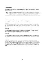
6. Installation
Instructions for how to mount the camera are described in the quickstart guide for the relevant IP
camera IPCBXXXX.
When mounting the dome camera IPCB74500 please make sure that the desiccant
bag supplied is placed inside the camera before placing on the dome. The bag must
be placed close to the base plate. The bag must not be in the field of view of the
lens. The bag must not be placed directly behind the lens or the camera board.
6.2
Routing the cables
You must pay attention to the following instructions when laying the cables:
IPCB24500
A break-out panel for feeding the cable is located on the base plate for laying the cables at the
side. Use pliers to remove the break-out panel. Use a file to smooth out the edges of the break-
out panel.
IPCB34500
A break-out panel for feeding the cable is provided for laying the cables at the side. Use a flat,
narrow screwdriver to remove the break-out panel from the plastic.
IPCB64500
A break-out panel for feeding the cable is located on the base plate for laying the cables at the
side. Use pliers to remove the break-out panel. Use a file to smooth out the edges of the break-
out panel.
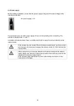
IPCB72500
For this type of camera, the cable is intended to be laid at the side or concealed. There are
openings at the side and on the base for this. The unused opening is sealed using a blind plug.
For installation the supplied cable gland must be used (for the side and base) in accordance with
protection class IP66. When using the optional wall bracket (TVAC31310), the cable gland may
be omitted, as the wall bracket panel and dome camera have been manufactured to fit together
tightly.
Summary of Contents for IPCB24500
Page 13: ...13 5 3 bersicht Anschl sse Bedienelemente Vorder R ckseite IPCB24500...
Page 14: ...14 IPCB34500...
Page 15: ...15 IPCB64500...
Page 16: ...16 IPCB74500...
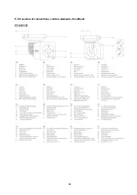
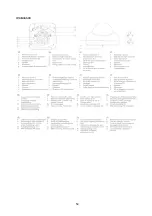
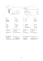
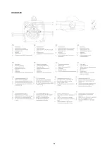
Page 58: ...58 5 3 Overview of connections control elements front back IPCB24500...
Page 59: ...59 IPCB34500...
Page 60: ...60 IPCB64500...
Page 61: ...61 IPCB74500...
Page 103: ...103 5 3 Vue d ensemble des raccordements l ment de commande face avant et arri re IPCB24500...
Page 104: ...104 IPCB34500...
Page 105: ...105 IPCB64500...
Page 106: ...106 IPCB74500...
Page 145: ...145 5 3 Overzicht aansluitingen bedieningselementen voor achterzijde IPCB24500...
Page 146: ...146 IPCB34500...
Page 147: ...147 IPCB64500...
Page 148: ...148 IPCB74500...
Page 187: ...187 5 3 Oversigt over tilslutninger betjeningsenheder for bagside IPCB24500...
Page 188: ...188 IPCB34500...
Page 189: ...189 IPCB64500...
Page 190: ...190 IPCB74500...
Page 232: ...232 5 3 Panoramica collegamenti elementi di comando lato anteriore posteriore IPCB24500...
Page 233: ...233 IPCB34500...
Page 234: ...234 IPCB64500...
Page 235: ...235 IPCB74500...


