4
7. Cut off the round connector end of the line cord and strip the wires ¼ inch.
Tin both wires with solder.
Slip on length of black heat shrink on each of the two stripped wires.
Solder the two stripped line cord wires to the red wires of the transformer.
Cover the bare wire joints with the heat shrink and heat them securely in place.
8. Insert coming in from the bottom of the PCB throughthe large strain relief hole beside the power
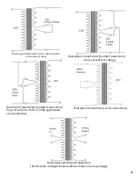
switch the two blue and one black transformer secondary wires.
9. Solder the black wire to the center connection and the two blue wires to the outside connections.
10. Place on the LM317 the heat sink clip.
11. Solder the terminal connection blocks and flick the switch to off position (pointing downwards in
reference to the Vanier logo) if not already done.
12. Connect into the wall socket and check the transform for heat inspection or shortage.
13. Flick the switch on and test the LM317 of heat inspection and led indication light is turned on.
14. Measure the output of the DC signal and adjust with the potentiometer.
15. Turn off the switch to ensure that there is no voltage being outputted.
16. Turn on the switch and measure the AC voltage.
17. Congratulation you now have a power supply, if it didn’t work please do not panic and read the
FAQ section.
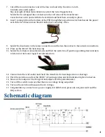
Schematic diagram
Summary of Contents for AK-10
Page 16: ......


