


30
31
Situation
Check Items
Solution
Fault LED
Read the error code (see
next page) displayed by
the combination of LEDs,
and verify the fault as
follows.
1. Er05,Er39
1. Check for proper battery
connection. Measure battery
voltage to ensure that batteries
are charged and healthy.
Recharge batteries for 8 hours if
necessary. Simulate utility outage
to verify that UPS is able to
provide DC backup. Otherwise
consult your local dealer right
away.
2. Overload
2. Disconnect some non-critical
loads from the UPS output until
the overload ceases. Check if
there is any short circuit between
cables due to broken cable
insulation. Replace the cables if
necessary.
3. Er11 (UPS Over
Temperature)
3. Remove any objects obstructing
the ventilation louvers. Verify that
the cooling fans are working
properly. Contact your local
dealer to replace the fans if
necessary.
4. Site wiring/Ground fault 4. Check if the “L” and “N” phases of
the utility AC source have been
wrongly wired or if the Ground-
Neutral voltage exceeds the
limits.
5. Er14 (Fans out of order) 5. Verify that the ventilating fans are
functioning properly. Do not
attempt to replace the fans
yourself. Contact your local dealer
for replacement.
6.Other error codes
6. Consult your local dealer for
assistance.
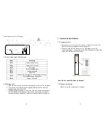
Utility Condition
UPS Operating Mode
LEDs
Normal
Working power starts after
approximately 5 seconds, LEDs on the
panel will blink and fans will start. Press
the ON button for 1-5 seconds. The
UPS starts up normally.
、
、
and
LEDs
remain lit
Abnormal (under or
over voltage or
absent)
Rectifier and charger stop operating.
Battery discharges via DC-DC boost
circuit and supplies Inverter. Loads
continue to receive supply from
Inverter. Alarm buzzer beeps. UPS now
in battery mode.
LED off, LED
illuminated
Utility abnormal or
absent, or battery
voltage low
Rectifier and charger stop operating.
Battery discharges via DC-DC boost
circuit and supplies Inverter. Alarm
buzzer beeps quickly, indicating battery
power low and Inverter may stop
supplying soon.
LED off, and
LEDs illuminated
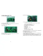
5. UPS System Block Diagram
Figure 4.1
Figure 4.1 illustrates the True On-Line Double Conversion architecture of the
UPS system. The major modules consist of:
1) An AC-to-DC power converter (rectifier) with PFC control circuit
2) A DC-to-AC high frequency inverter
3) An intelligent battery charger
4) A bank of stationary, maintenance-free batteries
5) A DC-to-DC push/pull converter control circuit
6) A static bypass loop
7) Input and output EMI filters
The table below provides a summary of the UPS operating modes under
various utility AC power source and battery conditions.
6. Maintenance Guide
6.1 Troubleshooting
If the UPS malfunctions during operation please check that all lines are
connected properly and that the utility specifications are correct. Then check the
table below for solutions. Should the problem persist please contact your local
dealer for assistance.
Summary of Contents for ARES RT-1K
Page 22: ...43 42 192321172024002...