Ablerex ARES RT-1K User Manual Download Page 10

18 

19 


4.3.1.3 Shutdown 


1.   Shutdown in AC Mode 

Press and hold the OFF button ‘

’ for five seconds until the buzzer beeps. 

The UPS will cut the power supply to the outlets. The ventilating fans will continue 
to  operate.  Switch  off  the  AC  power  source.  The  ventilating  fans  will  stop.  The 
UPS is now completely shut down. 


2.   Shutdown in DC Mode 

Press and hold the OFF button ‘

’ for five seconds until the buzzer beeps. 

The UPS will cut the power supply to the outlets. The LEDs will turn off, and the 
ventilating fans will stop after ten seconds and the ±BUS discharge is below 42 V. 
The UPS is now completely shut down. 


4.3.1.4 Self Testing in AC Mode 


After the UPS has been successfully started in AC mode, press and hold the 

Self-Test button ‘

’ for five seconds until the buzzer beeps. The        LED will 

shine to indicate that the self-test is in progress. When the self-test is completed 
the UPS will return to AC mode. If there were no faults or abnormal conditions 

then the LED indicators  


and  


LEDs will turn off. 


Note: The main function of self testing is to run a discharge test on the 

batteries.


4.3.2 LCD Panel 
4.3.2.1 Line mode start up 


1. Please ensure the outlet of power source is proper grounded. 
2. Ensure the voltage rating of power source is matched with UPS spec. 
3. Plug in UPS to the AC source 
4. UPS will start initializing after AC input power is available 5 seconds. 

LED/LCD indicator will be all lit and dim once and fan will start spinning. 
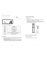
Full LCD display looks as below figure: 


5. Press  UPS               button  and  hold  untill  twice  beep  heard,  UPS  begins 

starting  procedures  for  5  seconds.    LCD  display  will  show  as  below 

figure-A  and  then  figure-B  sequentially.     LEDs  


will  light  up  to 

indicate   that   the   Utility   and   the   Bypass   are   normal.   And   then 
"  ","      ","       LED remain lit during figure-B LCD display. 


A


B


When you see figure-B means the starting up procedure is finished.   Please ensure 
UPS recharge in line mode for at least 4 hours for fully recharged before the first 
backup test if it’s a new installed unit.

Summary of Contents for ARES RT-1K

Page 1: ...t Explanation 12 4 Installation and Operation 13 4 1 Unpacking 13 4 2 Selecting Installation Position 16 4 3 Operation 17 5 UPS System Block Diagram 30 6 Maintenance Guide 31 6 1 Troubleshooting 31 6...

Page 2: ...rom obstruction and do not place anything on top of the UPS Keep the UPS rear panel 20 cm away from the wall or other obstructions 8 Install the UPS in a ventilated area ideally exchanging 5 m 3 of ai...

Page 3: ...with space constraints 2 This UPS is equipped with fully digital control logic for greater functionality and enhanced power protection Digital signal processing DSP also provides the UPS with powerful...

Page 4: ...attery and Load Function Mode indicates load capacity is 75 3 In Error Code Function Mode indicates Error Code 4 Load LED 1 Indicates UPS outlets are enabled and ready to supply loads 2 In Battery and...

Page 5: ...intermediately or Bypass to Inverter when the UPS is on Line Mode and the Bypass Voltage Window is Normal Item Sign Description LCD Display Green LED steadily lights up to indicate that the Utility in...

Page 6: ...t Measurement Display 10 Indicates the item to be measured 11 Battery Abnormal 12 Battery Low 13 Testing 3 1 3 LCD displayer description 3 2 Rear Panel ARES RT 230V 1K 2K 3K 1 Emergency Power Off EPO...

Page 7: ...highest priority first 1 EPO input port 2 Optional interface card 3 Optional USB 4 RS 232 4 Installation and Operation Please read the Safety Instruction guide pages 2 and 3 before installing the UPS...

Page 8: ...14 15 4 1 1 Installation Instructions Tower installation Rack Mount installation Step 1 Step 2 Step 3...

Page 9: ...ss and hold the ON button for approximately one second to start the UPS The buzzer will beep and the LED indicators and will shine after 1 5 seconds The start up procedure is now completed and the UPS...

Page 10: ...AC mode If there were no faults or abnormal conditions then the LED indicators and LEDs will turn off Note The main function of self testing is to run a discharge test on the batteries 4 3 2 LCD Panel...

Page 11: ...ocedure If the 2 nd button confirmation not be finished within 10 seconds after 1 st twice beeps UPS will not cold start and shut off after 10 seconds 2 5 seconds after cold starting amber LED will be...

Page 12: ...e procedures to release UPS from locked up status are as below L a Check and record the error code b Check user s manual to understand possible cause solve the problem or call service provider c Press...

Page 13: ...igure R1 Self test figure S1 Bypass Voltage Windows figure T Output Frequency Synchronization Window figure U Inverter Output Voltage figure V1 UPS Operation Mode figure W Output Voltage Micro Tune Va...

Page 14: ...Please refer specification for the detail 4 3 3 5 Figure T indicates the bypass frequency window of the Inverter Output The acceptable setting values are 3 Hz and 1 Hz 4 3 3 6 Figure U indicates the...

Page 15: ...vailable Press Off key and hold until twice beeps heard UPS output will shut off UPS will stay in standby mode fan s keep spinning and battery will be remained recharging if AC input still available a...

Page 16: ...s LEDs on the panel will blink and fans will start Press the ON button for 1 5 seconds The UPS starts up normally and LEDs remain lit Abnormal under or over voltage or absent Rectifier and charger sto...

Page 17: ...lty 1 Do not use the power strip 2 Replace the wall receptacle cord plug Strange noise or smell Immediately shut down the whole system Disconnect the power from the UPS and call for service UPS is una...

Page 18: ...odes and Their Meanings Code Meaning Er05 Battery weak or faulty Er06 Output short circuited Er07 EPO mode Er11 UPS over temperature Er12 Inverter overload Er14 Fan errors Er39 When UPS start process...

Page 19: ...y Normal normally open contact 4 Inverter On 5 Battery Low 6 Battery Bad or Abnormal 7 UPS Alarm 8 Common 9 Shutdown UPS positive signal 10 Shutdown UPS negative signal 8 3 2 The shutdown function wil...

Page 20: ...oad 7 at full non linear load Output Waveform Pure sine wave Outlets 3 10 A IEC 320 C13 6 10 A IEC 320 C13 6 10A IEC 320 C13 1 16A IEC 320 C19 Overload Capacity tolerance 1 Line Mode 105 continuous 10...

Page 21: ...dard LED Optional Normal Battery Bypass Self Test Battery Weak Bad Site Wiring Fault Fault Overload and Load Battery Level Optional Programmable Outlet1 Programmable Outlet2 4 Button Optional ON OFF S...

Page 22: ...43 42 192321172024002...

Reviews: