background image

|     Installation  –   

Affixing the label in accordance with DIN EN 17186-2019

26

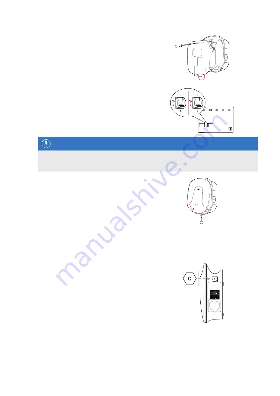
Replace the electronic components cover onto the 

housing base and fix it into place with the screw 

you removed in 

Step 3

.

10 

Switch the electricity supply of the wallbox back on.

NOTE

Setting up communication via LTE USB stick

Setting up the LTE USB stick for use with your wallbox is described from section "Setting up data communica-

tion" on page 34 onwards.

11 

Hook the housing cover onto the upper edge of the 

housing base and lock it using the housing cover 

key.

Affixing the label in accordance with DIN EN 17186-2019

In accordance with DIN EN 17186-2019, a graphical indication of the compatibility of vehicles and the charging infra-

structure is mandatory for commercial use. Your charging station therefore comes with a sticker which the operator 

must position near the charge point after the installation has been completed.

Wallbox eMH2 with charging socket


ƒ

One sticker with black writing on a white background 

is supplied for this variant.


ƒ

ABL recommends affixing the sticker in the position 

shown on the right-hand side. 

Summary of Contents for Wallbox eMH2

Page 1: ...Article No 0301764_EN_c Wallbox eMH2 Installation manual EN...

Page 2: ...sche Elektrozubeh r GmbH Co KG Albert Bu ttner Stra e 11 91207 Lauf an der Pegnitz Germany 49 0 9123 188 0 49 0 9123 188 188 info abl de www ablmobility de Customer Service 49 0 9123 188 0 service abl...

Page 3: ...24 Affixing the label in accordance with DIN EN 17186 2019 26 Configuring the Wallbox eMH2 28 Stand alone operation of a Controller wallbox 28 Stand alone operation of an Extender wallbox 28 Operation...

Page 4: ...ions 54 Allocation schematic from spring terminal to Easy2Install interface 55 Data cabling via LOMK218 55 Copyright and disclaimer 56 Dimensions 56 Drilling template 57 CE certification and complianc...

Page 5: ...eparately available accessory compo nents on our website at www ablmobility de Please visit https www ablmobility de Intended use The Wallbox eMH2 is used for charging private or company vehicles in y...

Page 6: ...marked with this symbol indicate further important information and features necessary for successful operation Actions marked with this symbol should be carried out as required Passages marked with t...

Page 7: ...y disregard of this instruction represents a safety risk fundamentally breaches the guarantee provisions and may void the warranty with immediate effect Malfunctions affecting the safety of persons co...

Page 8: ...lectrical components proof of completion of an ABL training course may be required For this purpose please contact ABL technical support see Contact on page II NOTE Changes to functions and design fea...

Page 9: ...rom page 52 Identifying your wallbox The model variant of the Wallbox eMH2 can be unambiguously identified on the rating plate located on the inside of the housing cover Please verify the information...

Page 10: ...ytt ohje Turvallisuusohjeet RO Instruc iuni de utilizare Indica ii privind siguran a NL Gebruiksaanwijzing Veiligheidsinstructies GR RU NO Bruksanvisning Sikkerhetsanvisninger HU Haszn lati tmutat Biz...

Page 11: ...g receptacle for installation on an exterior wall or the mounting pole POLEMH3 h 187 mm w 76 mm d 105 mm E3BLTE1 Accessory package with LTE USB stick and LTE antenna for installation in ABL Controller...

Page 12: ...according to IEC 62196 2 up to 20 A 240 415 V AC 3 phase length ca 7 m LAKK2K1 Type 2 to Type 1 adapter cable according to IEC 62196 2 up to 32 A 230 V AC single phase length ca 4 m You can find furt...

Page 13: ...e working steps described in this manual and recognise potential hazards Installation site requirements Your wallbox is suitable for outdoor use Please note however that the permissible ambient condit...

Page 14: ...nections on page 19 Tools and accessories required For mechanical installation you will need the following components included with the wallbox Drilling template 1 pc T20 panhead screws 6 60 mm 4 pcs...

Page 15: ...s Always observe the 5 safety rules 1 Cut power source 2 Secure all cut off devices 3 Verify absence of voltage 4 Ground and short circuit 5 Cover or bar access to adjacent components under voltage Pr...

Page 16: ...to prepare the wallbox 7 Open the housing cover of the wallbox with the housing cover key and put it aside 8 Loosen the screw of the internal electronic compo nents cover using the screwdriver Torx an...

Page 17: ...u inserted at the installation site in Step 6 12 Fix the housing base to the mounting surface by inserting the two remaining panhead screws into the two lower fixing points using the screwdriver or el...

Page 18: ...tem Designation Conductor colour Marks for Phase 1 current carrying conductor Brown 5 L1 Phase 2 current carrying conductor Black 3 L2 Phase 3 current carrying conductor Grey 1 L3 Neutral Blue N Prote...

Page 19: ...e RJ45 ports of the Easy2Install interfaces called E2I in the following from mid 2021 NOTE Data bus system compatibility The Wallbox eMH2 bus interfaces are completely downstream compatible Wiring up...

Page 20: ...der wallbox NOTE Continuation of the wiring diagram Connect all subsequent Extender wallboxes according to this method except for the last Extender wallbox 3 Connect the RJ45 plug of the incoming data...

Page 21: ...RCCB and the MCB inside the Wallbox eMH2 and switch the pivot levers to position I if necessary 2 Measure the voltage at the RCCB terminals using the voltage tester y In single phase installations th...

Page 22: ...ion N PE L1 L2 L3 The installation of the Wallbox eMH2 is now complete and the wallbox is ready for operation Connecting the E3BWLAN For integration into an existing WiFi network any Controller wallbo...

Page 23: ...witch in the left hand central connections area on the inside of the housing cover of the wallbox and insert the E3BWLAN into the Type A socket of the switch y If the 5V USB switch is already occupied...

Page 24: ...installation of its LTE mobile network antenna as well as setting up communication see from Set up via the Charge Point Administration application on page 31 but not the configuration of the associate...

Page 25: ...ace 4 Degrease the area on the right hand side of the in ternal lining using an alcohol swab 5 Remove the rear protective foil from the LTE anten na and stick it to this position 6 Lay the antenna cab...

Page 26: ...g cover onto the upper edge of the housing base and lock it using the housing cover key Affixing the label in accordance with DIN EN 17186 2019 In accordance with DIN EN 17186 2019 a graphical indicat...

Page 27: ...affixing the sticker in the position shown on the right hand side NOTE Further information on labelling The charging cables optionally available from ABL are marked accordingly by default In the case...

Page 28: ...nder wallbox for stand alone operation with out Controller or backend You can download the ABL Configuration Software free of charge in the Service All downloads Software section at www ablmobility de...

Page 29: ...8 8 8 Extender 8 9 9 9 Extender 9 10 10 10 Extender 10 11 11 11 Extender 11 12 12 12 Extender 12 13 13 13 Extender 13 14 14 14 Extender 14 15 15 15 Extender 15 16 16 16 With this wallbox the upper li...

Page 30: ...omputer via the configuration kit CONF CAB see next section Data cable connection with the computer To connect the Wallbox eMH2 to a Windows PC you will need the configuration kit CONFCAB separately a...

Page 31: ...d the current version of the software and follow the instructions in the manual which is embedded in the software and also contained in the installation folder https www ablmobility de en download neu...

Page 32: ...ttp 169 254 1 1 8300 This opens the Charge Point Administration online application where you are automatically logged in with the Owner role y If you are unable to connect to the application check you...

Page 33: ...the system configuration Repeat these steps to add all additional Extender charging stations in the system 8 Navigate to the bottom of the Products Instal lation tab and click the Create new configura...

Page 34: ...ur Controller Extender system and configured for load man agement To communicate with a backend you will also need to set up the Connectivity in the Charge Point Ad ministration application Setting up...

Page 35: ...reached via the MAC address of the Controller charging station The Controller Extender system must be connected via a suitable CAT cable to a router with Internet access to which your computer is also...

Page 36: ...e Controller charging station 1 2 3 4 Controller with Extender charging station s 1 2 LTE 1 2 3 4 Backend e g reev In order to establish a mobile network connection with an OCPP backend a suitable SIM...

Page 37: ...ellular tab and delete all data for the mobile access point APN if pres ent 2 Switch to the Connectivity WLAN tab and enter the information for Service Set Identifier SSID and the Passphrase for the n...

Page 38: ...mmunication is set up via WSS you must check that the TLS certificates are correct and upload the server certificate if necessary Proceed as follows to set up communication with the backend 1 Click th...

Page 39: ...ch in card 1 pc and RFID user cards 4 pcs using the ABL Configuration Soft ware Using the teach in card ID tag cards can be registered on the user list of the wallbox and then used to authorise chargi...

Page 40: ...list or if no further cards can be registered in the memory of the wallbox the Wallbox eMH2 will emit one sustained acoustic signal ca 1 second long If required you can reset the user list saved in th...

Page 41: ...e compartment Open the charging inlet at the vehicle and plug in the charging connector y Wallbox with charging socket Open the charging inlet at the vehicle and plug in the charging connector Then op...

Page 42: ...indicators of the wallbox y When the wallbox initiates the charging procedure following a request by the vehicle the blue LED is ON y When the charging procedure is paused or com pleted the blue LED...

Page 43: ...dy for operation the green LED pulsates NOTE Removing the charging cable from a wallbox with charging socket If the wallbox has a charging socket the charging cable should be unplugged from the chargi...

Page 44: ...D flashing three times and the blue LED flashing once Cause Suggested solution The firmware has detected a disallowed operat ing state during an initial or periodic self test Switch the RCCB of the wa...

Page 45: ...e the charging socket of the wallbox The wallbox automatically reinitiates the self test after 30 seconds after two failed self tests the charging procedure is terminated permanently Should the error...

Page 46: ...rsists the wallbox and or the vehicle must be checked please contact a quali fied specialist electrical contractor or a specialist repairer Error F10 Description Flash pattern Per cycle the red flashe...

Page 47: ...o a value above 20 A If the error cannot be resolved please contact the specialist electrical contractor who has carried out the installation of your wallbox and any accessories Errors F16 and F17 Des...

Page 48: ...For wallboxes with charging socket also remove the charging connector from the charging socket of the wallbox and plug it back in y Contact a qualified specialist electrical contractor to have the er...

Page 49: ...ide 2 Open the access flap of the internal electronic com ponents cover 3 Locate and press the push button engraved T or marked Test y The RCCB must now trip and flick its pivot lever into the centre...

Page 50: ...tion y Also flip the pivot lever of the internal MCB to position 0 4 Close the access flap hook the housing cover onto the upper edge of the housing base and lock it using the housing cover key 5 Open...

Page 51: ...function of its charging interfaces checked Use only a dry cloth for cleaning the wallbox Do not use aggressive cleaning agents waxes or solvents such as cleaning fluid or paint thinner as they may du...

Page 52: ...ng trips RCD RFID ISO14443A B UID 4 Byte 7 Byte only Backend communication OCPP 1 6 via LAN or LTE WIFI optional Compliance standards IEC 61851 1 Control customisation Internal RS485 interface bus sys...

Page 53: ...ngth IK08 Dimensions H W D 437 328 170 mm Weight per unit approx 8 kg approx 10 kg Structurally identical variant with one charging socket with shutter 2W2242 Stand alone series Model code 2W2222 Rate...

Page 54: ...cles Trademarks All trademarks mentioned in this manual including those that may be protected by third parties are without restric tion subject to the regulations of the respectively applicable tradem...

Page 55: ...of terminal ABL bus allocation PIN allocation Top view of RJ45 plug 8 1 1 2 3 4 5 6 7 8 B M A METER B M A CONTROL CONTROL A 1 8 1 1 2 3 4 5 6 7 8 B M A METER B M A CONTROL CONTROL M 3 6 CONTROL B 2 ME...

Page 56: ...ration Energy meter and LGW Copyright and disclaimer Copyright 2021 Version 0301764_EN_c date 06 08 2021 All rights reserved Any information contained in this manual may be changed without prior notic...

Page 57: ...allbox eMH2 comes with a drilling template see illustration below for marking the fixing points Should the drilling template have been lost you can obtain the drilling dimensions from the illustration...

Page 58: ...is displayed below Disposal advice The crossed out rubbish bin symbol indicates that electrical and electronic devices including accessories must be disposed of separate from household refuse The mate...

Page 59: ...Contents 59...

Page 60: ...MADE IN GERMANY ABL SURSUM Bayerische Elektrozubeh r GmbH Co KG Albert Bu ttner Stra e 11 91207 Lauf an der Pegnitz Germany 49 0 9123 188 0 49 0 9123 188 188 info abl de www ablmobility de...

Reviews: