| Configuring the Wallbox eMH2 –
Setting up data communication
34
12
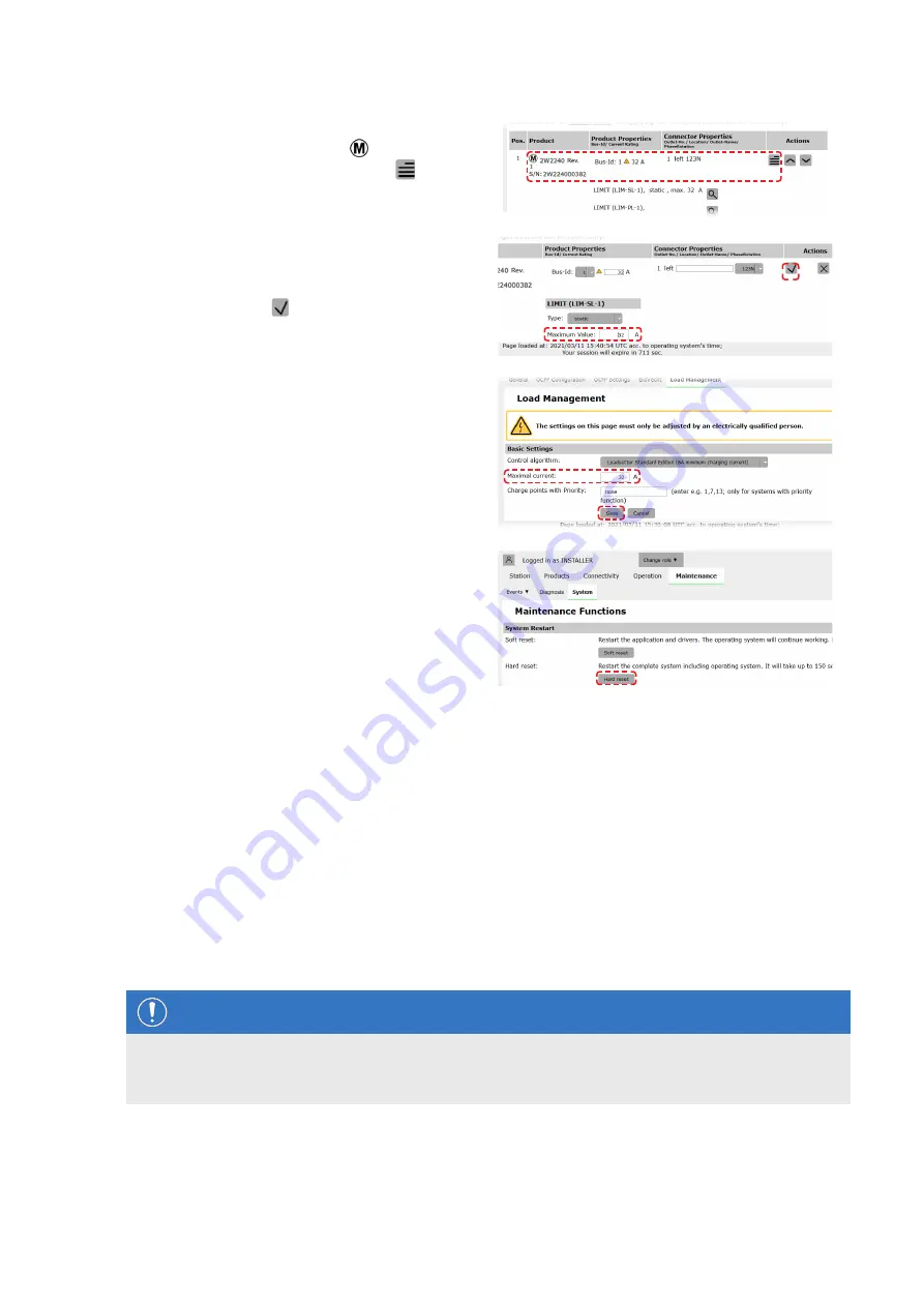
Switch to the
Products > Installation
tab, and,
in the
Actions
column, click the button for the
Controller charging station marked with .
13
In the
Maximum Value
field in the
LIMIT (LIM
SL-1)
section, enter the desired maximum current
(for example:
32 A
) for the entire system.
y
Confirm with the button on the right.
14
Switch to the
Operation > Load Management
tab and enter the same value in the
Maximum
Current
field in the
Basic Settings
section that
you entered for the
Maximum current
in step
13
(for example:
32 A
).
y
Confirm with the
Save
button.
15
Switch to the
Maintenance > System
tab and
click the
Hard reset
button in the
System Restart
section.
y
Your Controller/Extender system will now
restart with the selected settings.
The Extender wallboxes are now correctly registered in your Controller/Extender system and configured for load man-
agement. To communicate with a backend, you will also need to set up the
Connectivity
in the
Charge Point Ad-
ministration
application.
Setting up data communication
The Wallbox eMH2 offers three interfaces for data communication with an external network or a backend:
LAN (wired via internal RJ45 interfaces)
LTE (wireless via LTE USB stick
E3BLTE1
: preinstalled for bundle products, otherwise available separately, see
WiFi (wireless via separately available WiFi dongle
E3BWLAN
, see "Accessories" on page 10)
Data communication is also set up via the
Charge Point Administration
application: the application must therefore
be open and the connection to the Controller charging station established. You can carry out the working steps de-
scribed below either as
Owner
or
Installer
.
NOTE
Data communication for Controller charging stations only
Please note that Extender charging stations can only be integrated into a network via a Controller charging sta-
tion, not directly.


