

090810_ABI-ET2001_QSG_ML
English
Page 11
N.V.
abitana
S.A.
ENGLISH
P1
P2
P3
ISDN
L1
L2
P4
A
L2
ISDN-So
NT
So BUS
B
TA
ISDN-So
ISDN-So
B
TA
TO TELECOM
OPERATOR (ISDN)
Switch Nr.
Position
S1
A
S2
B
S3
B
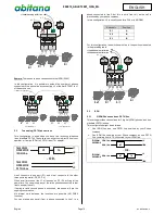
For this configuration, the switches must be in the positions indicated
in the preceding table.
5.3.2
All ISDN connections
This configuration distributes the ISDN (So Bus) to the 4 ports
P1
P2
P3
ISDN
L1
L2
P4
A
ISDN-So
NT
So BUS
A
ISDN-So
ISDN-So
A
ISDN-So
TO TELECOM
OPERATOR (ISDN)
Switch Nr.
Position
S1
A
S2
A
S3
A
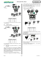
For this configuration, the switches must be in the positions, indicated
in the preceding table.
5.4
One phone lines (PSTN) connected to a priority
FAX/Modem
If you have one incoming line L2, and you have a FAX/Modem
connected to that line, you can use the feed-thru feature of that
equipment to disconnect the rest of the phones when a FAX
communication is in progress, or when the phone line is in use by a
Modem. This prevents disruption of the communication when someone
picks-up a phone while the line is in use by those devices. The feed-
thru line becomes L2’ in the drawing.
When a call arrives, all phones will ring (including FAX/Modem).
Depending on the configuration of the FAX/Modem, it will answer the
call after a specified number of rings. Anytime between the first ring
and that specific number of rings, you can answer the call by picking
up any of the phones connected to P2 ~ P4.
When the call has been answered by the FAX or Modem, phones
connected to P2 ~P4 (21’) will be disconnected.
P1
P2
P3
ISDN
L1
L2
P4
B
B
B
L2
L2’
L2’
L2’
NC
NC
L2 PUBLIC analog (PSTN) line
Switch Nr.
Position
S1
B
S2
B
S3
B
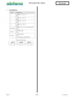
For this configuration, the switches must be in the positions, indicated
in the preceding table.
Important Remark:
This configuration is only valid in casee the FAX connected to P1
returns L2’ on pins 3 and 6 of the RJ45 connector.
P1
P2
P3
P4
L2
L2’
L2’
L2’
L2
L2’
RJ11/RJ12
Whenever the FAX is disconnected, all the phones connected to P2 ~
P4 are disconnected also.
If the FAX is disconnected (repair, maintenance, …) the configuration
must be changed (Select setting AAA).


