background image

Introduction 

1-3 

1-2. Layout Diagram 


User’s Manual 

Summary of Contents for LG80

Page 1: ...LG 80 Series LP 80 Series LG 80 LG 81 LP 80 LP 81 Intel Pentium 4 System Board Socket 775 User s Manual 4200 0457 01 Rev 1 00 ...

Page 2: ...onsequential damages arising from any defect or error in this manual or product Product names appearing in this manual are for identification purpose only and trademarks and product names or brand names appearing in this document are the property of their respective owners This document contains materials protected under International Copyright Laws All rights reserved No part of this manual may b...

Page 3: ... 2 8 4 Wake up Header 2 9 5 Serial ATA Connectors 2 10 6 Front Panel Audio Connection Header 2 11 7 Front Panel Switches Indicators Headers 2 12 8 Additional IEEE1394 Port Header 2 13 9 Additional USB Port Headers 2 14 10 Internal Audio Connector 2 15 11 Floppy and IDE Disk Drive Connectors 2 16 12 PCI Express x16 Slot 2 17 13 PCI Express x1 Slot 2 17 14 Back Panel Connectors 2 18 Chapter 3 BIOS S...

Page 4: ...LG 80 Series LP 80 Series ...

Page 5: ... only Integrated Intel Graphics Media Accelerator 900 supports DirectX 9 Supports ADD2 card 5 PCI Express x16 graphic Delivers up to 8GB s per direction for 3 5 times more bandwidth than AGP8X 6 SATA 3G Supports 4 ports Serial ATA 3 0Gb s data transfer rate Supports SATA AHCI providing native command queuing and native hot plug 7 Audio Onboard 7 1 channel Intel High Definition Audio CODEC Supports...

Page 6: ... 1x Parallel port connector 1x AUDIO1 connector Surround Left Surround Right Rear Left Rear Right Center Subwoofer 1x AUDIO2 connector Mic In Line In Line Out 4x USB connectors 1x RJ 45 LAN connector 1x IEEE 1394 connector For models LG 80 LP 80 only 1x VGA connector For models LG 80 LG 81 only 1x S P DIF Out For models LP 80 LP 81 only 13 Miscellaneous mATX form factor 245mm x 245mm Specification...

Page 7: ...Introduction 1 3 1 2 Layout Diagram User s Manual ...

Page 8: ...1 4 Chapter 1 1 4 Chapter 1 LG 80 Series LP 80 Series LG 80 Series LP 80 Series ...

Page 9: ...he best way to attach the board is to use with studs Only if you are unable to do this should you attach the board with spacers Line up the holes on the board with the mounting holes on the chassis If the holes line up and there are screw holes you can attach the board with studs If the holes line up and there are only slots you can only attach with spacers Take the tip of the spacers and insert t...

Page 10: ...way from the retention tab 2 Rotate the lever to fully open position 3 Use your right thumb on the bottom right side of the load plate and lift it up to fully open position 4 Use your right thumb and forefinger to grasp the CPU package Be sure to grasp on the edge of the substrate and face the Pin 1 indicator toward the bottom left side Aim at the socket and place the CPU package vertical down int...

Page 11: ...an assembly onto the socket Align the four fasteners toward the four mounting holes on the motherboard For detailed information on how to install your heatsink and fan assembly please refer to the instruction manual came packed with the heatsink and fan assembly you bought 10 Press each of the four fasteners down into the mounting holes 11 Rotate the fastener clock wise to lock the heatsink and fa...

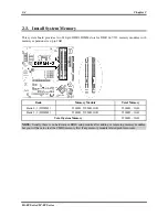
Page 12: ...GB Bank Memory Module Total Memory Bank 0 1 DIMM1 256MB 512MB 1GB 256MB 1GB Bank 2 3 DIMM2 256MB 512MB 1GB 256MB 1GB Total System Memory 256MB 2GB NOTE Usually there is no hardware or BIOS setup require after adding or removing memory modules but you will have to clear the CMOS memory first if any memory module related problem occurs LG 80 Series LP 80 Series ...

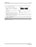
Page 13: ...e ejector tabs at both sides of the slot automatically snaps into the mounting notch Do not force the DIMM module in with extra force as the DIMM module only fit in one direction 5 To remove the DIMM modules push the two ejector tabs on the slot outward simultaneously and then pull out the DIMM module ATTENTION Static electricity can damage the electronic components of the computer or optional boa...

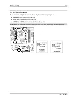
Page 14: ...at you may refer to WARNING Always power off the computer and unplug the AC power cord before adding or removing any peripheral or component Failing to so may cause severe damage to your motherboard and or peripherals Plug in the AC power cord only after you have carefully checked everything 1 ATX Power Input Connectors This motherboard provides two power connectors to connect ATX12V power supplie...

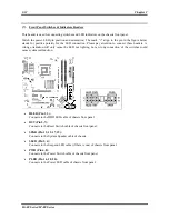
Page 15: ...de power to the cooling fans installed in your system CPUFAN1 CPU Fan Power Connector SYSFAN1 System Fan Power Connector AUXFAN1 AUXFAN2 Auxiliary Fan Power Connector WARNING These fan connectors are not jumpers DO NOT place jumper caps on these connectors User s Manual ...

Page 16: ...the CMOS memory Pin 1 2 shorted default Normal operation Pin 2 3 shorted Clear CMOS memory WARNING Turn the power off first including the 5V standby power before clearing the CMOS memory Failing to do so may cause your system to work abnormally or malfunction LG 80 Series LP 80 Series ...

Page 17: ...nction USB PWR1 Pin 1 2 shorted default Disable wake up function support at USB1 port Pin 2 3 shorted Enable wake up function support at USB1 port USB PWR2 Pin 1 2 shorted default Disable wake up function support at USB2 port Pin 2 3 shorted Enable wake up function support at USB2 port User s Manual ...

Page 18: ...rs These connectors are provided to attach one Serial ATA device at each channel via Serial ATA cable For more information on how to configure the function mode for SATA please refer to the item in the BIOS menu LG 80 Series LP 80 Series ...

Page 19: ...o front panel by the extension cable provided with the chassis To use the audio connector at rear panel disconnect the extension cable attach the jumpers back at pin 5 6 and pin 9 10 default setting Pin Pin Assignment Pin Pin Assignment 1 Audio Mic 2 Ground 3 Audio Mic Bias 4 VCC 5 Speaker Out Right Channel 6 Speaker Out Right Channel Return 7 X 8 NC 9 Speaker Out Left Channel 10 Speaker Out Left ...

Page 20: ...ll only cause the LED not lighting but a wrong connection of the switches could cause system malfunction HLED Pin 1 3 Connects to the HDD LED cable of chassis front panel RST Pin 5 7 Connects to the Reset Switch cable of chassis front panel SPKR Pin 13 15 17 19 Connects to the System Speaker cable of chassis SLED Pin 2 4 Connects to the Suspend LED cable if there is one of chassis front panel PWR ...

Page 21: ...394 Port Header This header provides one additional IEEE1394 port connection through an extension cable and bracket Pin Pin Assignment Pin Pin Assignment 1 TPA0 2 TPA0 3 Ground 4 Ground 5 TPB0 6 TPB0 7 12V 8 12V 9 NC 10 Ground User s Manual ...

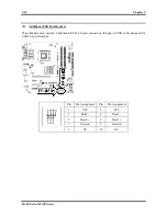
Page 22: ...headers each provide 2 additional USB 2 0 ports connection through an USB cable designed for USB 2 0 specifications Pin Pin Assignment Pin Pin Assignment 1 VCC 2 VCC 3 Data0 4 Data1 5 Data0 6 Data1 7 Ground 8 Ground 9 NC 10 NC LG 80 Series LP 80 Series ...

Page 23: ...Hardware Setup 2 15 10 Internal Audio Connector This connector connects to the audio output of internal CD ROM drive or add on card User s Manual ...

Page 24: ...ort and the floppy connector Each of the IDE port connects up to two IDE drives at Ultra ATA 100 mode by one 40 pin 80 conductor and 3 connector Ultra ATA 66 ribbon cables Connect the single end blue connector at the longer length of ribbon cable to the IDE port of this board the other two ends gray and black connector at the shorter length of the ribbon cable to the connectors of your hard drives...

Page 25: ...etup 2 17 12 PCI Express x16 Slot This slot is used to attach the next generation of graphics architecture 13 PCI Express x1 Slot This slot is used to attach the next generation of I O architecture User s Manual ...

Page 26: ...hannel audio system R L R R Rear Left Rear Right Connects to the rear left and rear right channel in the 7 1 channel audio system Cen Sub Center Subwoofer Connects to the center and subwoofer channel in the 7 1 channel audio system AUDIO2 Mic In Connects to the plug from external microphone Line In Connects to the line out from external audio sources Line Out Connects to the front left and front r...

Page 27: ...Right Connects to the rear left and rear right channel in the 7 1 channel audio system Cen Sub Center Subwoofer Connects to the center and subwoofer channel in the 7 1 channel audio system AUDIO2 Mic In Connects to the plug from external microphone Line In Connects to the line out from external audio sources Line Out Connects to the front left and front right channel in the 5 1 channel or regular ...

Page 28: ...2 20 Chapter 2 LG 80 Series LP 80 Series ...

Page 29: ...mory count begins and then the following message appears on the screen PRESS DEL TO ENTER SETUP If this message disappears before you respond restart the system by pressing Ctrl Alt Del keys or by pressing the Reset button on computer chassis Only when it failed by these two methods can you restart the system by powering it off and then back on After pressing Del key the main menu screen appears N...

Page 30: ...3 2 Chapter 3 3 2 Chapter 3 LG 80 Series LP 80 Series LG 80 Series LP 80 Series ...

Page 31: ... the Drivers Utilities CD that came packed with the motherboard The display shown in the following figure should appear after inserting the Drivers Utilities CD into your CD ROM drive if not enter My Computer CD ROM Drive double click autorun exe Please follow the on screen instruction User s Manual ...

Page 32: ...all the onboard LAN driver for Windows Operating System USB 2 0 Driver Update the USB 2 0 driver for Windows 2000 XP Operating System via the Windows Updating Program Manual View the user s manual in PDF file Utility Click to enter the sub screen for installing software ABIT Utility Click to enter the sub screen to install utilities like Flash Menu BIOS Update Utility and Hardware Doctor Browse CD...

Page 33: ...est the following three troubleshooting methods to discharge CMOS data recover the hardware default status and then make the motherboard working again No need to bother returning the motherboard to where you bought from or go through an RMA process Step 1 Switch off the power supply unit and then switch it on again after one minute If there is no power switch on the power supply unit disconnect it...

Page 34: ...art the system each time you insert a card until the system will not start Keep the VGA card and the interface card that caused the problem inserted on the motherboard remove any other cards or peripheral and start again If you still cannot start note the information related to both cards in the add on Card space provided and don t forget to indicate the motherboard model version BIOS identificati...

Page 35: ...aster Example In the HDD space check the box in the Brand space write Seagate in the Specifications space write ST31621A 1 6GB 8 CD ROM Drive Indicate the brand and specifications of your CD ROM drive Specify if it uses IDE1 or IDE2 and check in case you give no indication we will consider that your CD ROM is IDE2 Master Example In the CD ROM drive space check the box in the Brand space write Mits...

Page 36: ... Number Contact Person Fax Number E mail Address Model BIOS ID Motherboard Model No DRIVER REV OS Application Hardware Name Brand Specifications CPU HDD IDE1 IDE2 CD ROM Drive IDE1 IDE2 System Memory ADD ON CARD Problem Description LG 80 Series LP 80 Series ...

Page 37: ...ts have the best quality and compatibility In case you need service or technical support please understand the constraint we have and always check with the reseller who sold the product to you first To expedite service we recommend that you follow the procedures outlined below before contacting us With your help we can meet our commitment to provide the best service to the greatest number of ABIT ...

Page 38: ...und policies How they serve you is also a good reference for your next purchase 6 Contacting ABIT If you feel that you need to contact ABIT directly you can send email to the ABIT technical support department First please contact the support team for the branch office closest to you They will be more familiar with local conditions and problems and will have better insight as to which resellers off...

Page 39: ...elux Belgium Netherlands Luxembourg France Italy Spain Portugal Greece Denmark Norway Sweden Finland and Switzerland AMOR Computer B V ABIT s European Office Jan van Riebeeckweg 15 5928LG Venlo The Netherlands Tel 31 77 3204428 Fax 31 77 3204420 Sales sales abit nl Web Site http www abit nl Austria Czech Romania Bulgaria Slovakia Croatia Bosnia Serbia and Macedonia Asguard Computer Ges m b H Schma...

Page 40: ...it com tw 8 Reporting Compatibility Problems to ABIT Because of tremendous number of email messages we receive every day we are forced to give greater weight to certain types of messages than to others For this reason any compatibility problem that is reported to us giving detailed system configuration information and error symptoms will receive the highest priority For the other questions we regr...

Reviews: