background image

RTM ABIx EasyTeach

7 Creating a welding program

DE 

-

 9

7.2 Activating/deactivating programming mode

1

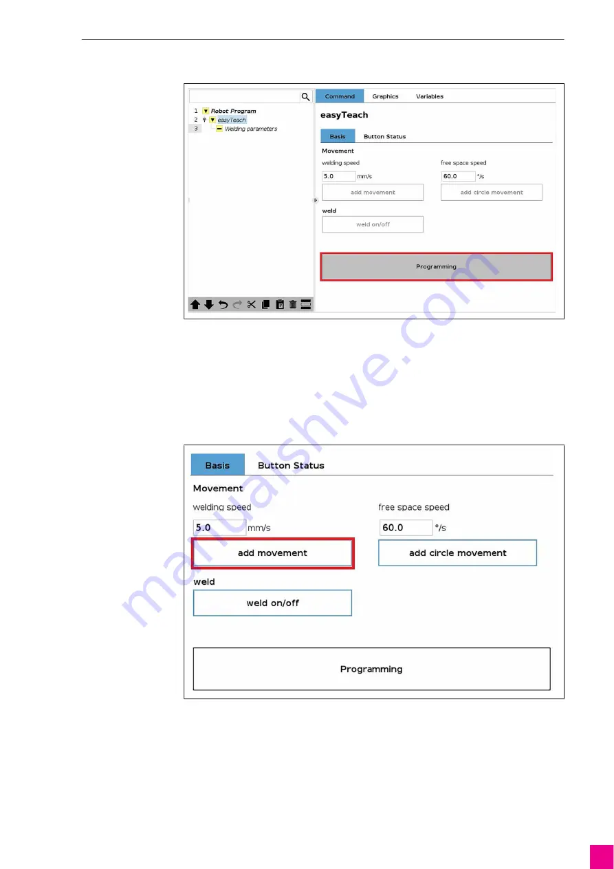
Press the <Programming> button to activate programming mode.

The program node is shown in yellow. The program can be started only when programming mode is ended.

2

Press the <Programming> button to deactivate programming mode.

7.3 Adding movement

Operation via operating panel

1

Deactivate <weld on/off> to integrate an axis movement.
Activate <weld on/off> to integrate a MoveP.

2

Move the robot arm to the desired position.

3

Press the <add movement> button to add a position.

Fig. 8

Activating programming mode

Fig. 9

Adding movement

Summary of Contents for RTM ABIx EasyTeach

Page 1: ...C H N O L O G Y F O R T H E W E L D E R S W O R L D www binzel abicor com DE Original Betriebsanleitung EN Original operating instructions RTM ABIx EasyTeach DE Multifunktionsflansch EN Multifunction flange ...

Page 2: ... Software konfigurieren DE 6 5 1 Tool Center Point TCP einrichten DE 6 5 2 Multifunktionsflansch aktivieren DE 6 5 3 Multifunktionsflansch konfigurieren DE 7 5 4 Einstellungen speichern DE 7 6 Roboter bewegen DE 8 7 Schweißprogramm erstellen DE 8 7 1 Geschwindigkeit einstellen DE 8 7 2 Programmiermodus aktivieren deaktivieren DE 9 7 3 Bewegung hinzufügen DE 9 7 4 Kreisbewegung hinzufügen DE 10 7 5...

Page 3: ...efährlichen Arbeitsschritten angegeben Je nach Art der Gefahr werden die folgenden Signalworte verwendet 2 Lieferumfang 1x Multifunktionsflansch inkl Befestigungsmaterial 1x Verbindungskabel 1x Betriebsanleitung Allgemeine Handlungsanweisungen Handlungsschritte die der Reihenfolge nach durchzuführen sind Aufzählungen Querverweissymbol verweist auf detaillierte ergänzende oder weiterführende Inform...

Page 4: ...automatisch mit dem URCap ab der Version 4 0 0 installiert Beipackzettel Installation und Anwendung URCap Abb 1 Aufbau und Funktion A Verbindungskabel B Brennerhalter C Taste Schweißfunktionen D Taste Bewegungsprogrammierung E Taste Bewegungsfreigabe Roboter F Befestigungsflansch Taste Bewegungsfreigabe Roboter E Mit der Taste wird der Roboter für das Bewegen von Hand freigegeben Taste Bewegungspr...

Page 5: ... Anschluss am Roboter B verbinden 3 Schweißbrenner G in Brennerhalter H einlegen und händisch fixieren 4 Klemmbügel F mit Zylinderschrauben E befestigen Anzugsdrehmoment max 4 Nm Abb 2 Multifunktionsflansch montieren A Roboter B Anschluss Roboter C Verbindungskabel D Multifunktionsflansch E 4x Zylinderschrauben M5x20 F Klemmbügel G Schweißbrenner H Brennerhalter I 4x Zylinderkopfschrauben M6x25 A ...

Page 6: ...itet werden soll zwei TCPs anlegen Einen mit korrekt hinterlegten Rx Ry Rz und einen für die Benutzung in Verbindung mit easyTeach 5 2 Multifunktionsflansch aktivieren 1 Menü Installation URCaps easyTeach auswählen 2 Erstellten TCP auswählen Dieser wird für alle mit easyTeach erstellten Bahnen verwendet 3 Checkbox Enable esayTech Hardware anhaken Die Eingänge am Multifunktionsflansch sind aktivier...

Page 7: ... einstellen Dem Werkzeugeingang 0 muss die Funktion Freedrive zugeordnet werden 3 Menü Installation I O Setup auswählen 4 In der linken Spalte den Eingang tool in 0 auswählen und unter Action Freedrive auswählen 5 4 Einstellungen speichern Die Einstellungen werden erst gespeichert wenn die Software heruntergefahren wird 1 Um die Software herunterzufahren am Bedienpanel die Power Taste drücken 2 Ab...

Page 8: ...ng deaktivieren 7 5 Schweißprozess ein ausschalten auf Seite DE 11 5 Programmiermodus deaktivieren 7 2 Programmiermodus aktivieren deaktivieren auf Seite DE 9 7 1 Geschwindigkeit einstellen 1 Menü Program UR Caps easyTeach auswählen In eingestellten Geschwindigkeiten werden dann in allen Bewegungen die mit easyTeach erstellt werden gesetzt Um den Roboter von Wegpunkt zu Wegpunkt zu bewegen Taste B...

Page 9: ...n wenn der Programmiermodus beendet wurde 2 Um den Programmiermodus zu deaktivieren Programming Button erneut drücken 7 3 Bewegung hinzufügen Bedienung über Bedienpanel 1 Um eine Achsbewegung einzufügen weld on off deaktivieren Um eine FahreP einzufügen weld on off aktivieren 2 Roboterarm an die gewünschte Position bewegen 3 Um einen Wegpunkt hinzuzufügen add movement Button drücken Abb 8 Programm...

Page 10: ...kt der Kreisbewegung Bedienung über Bedienpanel 1 Roboterarm an die gewünschte Position bewegen 2 Um den Durchgangspunkt einer Kreisbewegung hinzuzufügen add circle movement Button drücken Bedienung über Multifunktionsflansch 1 Roboterarm an die gewünschte Position bewegen 2 Um einen Wegpunkt hinzuzufügen Taste Bewegungsprogrammierung am Multifunktionsflansch kurz drücken Abb 10 Kreisbewegung hinz...

Page 11: ...chsbewegung Bedienung über Bedienpanel 1 Um den Schweißprozess zu starten weld on off Button drücken 2 Um den Schweißprozess zu stoppen weld on off Button erneut drücken Bedienung über Multifunktionsflansch Abb 11 Schweißprozess ein ausschalten 1 Um den Schweißprozess zu starten Taste Schweißfunktionen am Multifunktionsflansch kurz drücken 2 Um den Schweißprozess zu stoppen Taste Schweißfunktionen...

Page 12: ...kann ein Schweißhefter erzeugt werden WARNUNG Verblitzung der Augen durch Lichtbogen Der erzeugte Lichtbogen kann ihre Augen schädigen Überprüfen und tragen Sie Ihre persönliche Schutzausrüstung Augenschutz 1 Taste Schweißfunktionen am Multifunktionsflansch für die Dauer des Schweißprozesses gedrückt halten ...

Page 13: ... 8 X1 WH GY YE BN GN PK BU RD RD 1 2 3 4 5 6 7 8 GY Vin OUT GND 400 1947 0 13 14 T3 GY 13 14 T2 13 14 T1 GY YE GN n c n c n c Isoliert mit Schrumpfschlauch insulated with shrinking tube M8 8pol Taster wird direkt auf Platine gelötet switch is directly soldererd to PCB ...

Page 14: ...uring the software DE 6 5 1 Setting up the tool center point TCP DE 6 5 2 Activating the multifunction flange DE 6 5 3 Configuring the multifunction flange DE 7 5 4 Saving settings DE 7 6 Moving the robot DE 8 7 Creating a welding program DE 8 7 1 Setting the speed DE 8 7 2 Activating deactivating programming mode DE 9 7 3 Adding movement DE 9 7 4 Adding circle movement DE 10 7 5 Switching the wel...

Page 15: ...instructions are divided into four different levels and shown prior to potentially dangerous work steps The following signal words are used depending on the type of hazard 2 Scope of delivery 1 multifunction flange incl attachment materials 1 connecting cable 1 operating instructions General instructions Action s to be carried out in succession Lists Cross reference symbol refers to detailed suppl...

Page 16: ...utomatically installed with the URCap from version 4 0 0 Installing and using URCap instruction leaflet Fig 1 Assembly and use A Connecting cable B Torch mount C Welding functions button D Movement programming button E Robot movement release button F Mounting flange Robot movement release button E This button is used to release the robot for manual movement Movement programming button D This butto...

Page 17: ...onnection cable C to the robot connection B 3 Insert the welding torch G in the torch mount H and fix manually 4 Tighten the clamp F with cylinder head screws E tightening torque max 4 Nm Fig 2 Mounting the multifunction flange A Robot B Robot connection C Connecting cable D Multifunction flange E 4 cylinder head screws M5x20 F Clamp G Welding torch H Torch mount I 4 cylinder head screws M6x25 A B...

Page 18: ... TCP coordinate system should be worked with as well one with the correctly assigned Rx Ry Rz and one for use in conjunction with easyTeach 5 2 Activating the multifunction flange 1 Select menu Installation URCaps easyTeach 2 Select the created TCP This is used for all tracks created with easyTeach 3 Check the Enable easyTeach Hardware checkbox The inputs on the multifunction flange are activated ...

Page 19: ...Tool Output Voltage to 24 V The Freedrive function must be assigned to the tool input 0 3 Select menu Installation I O Setup 4 In the left hand column select the tool in 0 input and select Freedrive under Action 5 4 Saving settings The settings are saved only when the software is shut down 1 Press the power button on the operating panel to shut down the software 2 Confirm the prompt to save Fig 5 ...

Page 20: ...ment and deactivate after the movement 7 5 Switching the welding process on off on page DE 11 5 Deactivate programming mode 7 2 Activating deactivating programming mode on page DE 9 7 1 Setting the speed 1 Select menu Program URCaps easyTeach All movements created with easyTeach are then set in set speeds To move the robot from position to position press and hold down the Robot movement release bu...

Page 21: ...an be started only when programming mode is ended 2 Press the Programming button to deactivate programming mode 7 3 Adding movement Operation via operating panel 1 Deactivate weld on off to integrate an axis movement Activate weld on off to integrate a MoveP 2 Move the robot arm to the desired position 3 Press the add movement button to add a position Fig 8 Activating programming mode Fig 9 Adding...

Page 22: ...end point of the circle movement Operation via operating panel 1 Move the robot arm to the desired position 2 Press the add circle movement button to add the point of passage for a circle movement Operation via the multifunction flange 1 Move the robot arm to the desired position 2 Press the Movement programming button on the multifunction flange briefly to add a position Fig 10 Adding circle move...

Page 23: ...nt Operation via operating panel 1 To start the welding process press the weld on off button 2 To stop the welding process press the weld on off button again Operation via the multifunction flange Fig 11 Switching the welding process on off 1 To start the welding process briefly press the welding functions button on the multifunction flange 2 To stop the welding process briefly press again the wel...

Page 24: ...via the multifunction flange 9 Circuit diagram WARNING Stunning of eyes by arcs Arcs produced by welding can damage your eyes Check and wear your personal protective equipment eye protection 1 Press and hold down the Welding functions button on the multifunction flange for the duration of the welding process ...

Page 25: ...1 WH GY YE BN GN PK BU RD RD 1 2 3 4 5 6 7 8 GY Vin OUT GND 400 1947 0 13 14 T3 GY 13 14 T2 13 14 T1 GY YE GN n c n c n c Isoliert mit Schrumpfschlauch insulated with shrinking tube M8 8pol Taster wird direkt auf Platine gelötet switch is directly soldererd to PCB ...

Page 26: ...DE 14 Notes RTM ABIx EasyTeach Notes ...

Page 27: ...RTM ABIx EasyTeach Notes DE 15 Notes ...

Page 28: ...er Binzel Schweisstechnik GmbH Co KG Kiesacker 35418 Buseck GERMANY T 49 64 08 59 0 F 49 64 08 59 191 info binzel abicor com BAL 0947 0 2022 02 10 Importer UK ABICOR BINZEL UK ltd Binzel House Mill Lane Winwick Quay Warrington WA2 8UA UK T 44 1925 65 39 44 F 44 1925 65 48 6 info binzel abicor co uk ...

Reviews: