Abestorm Living Environment CTR100 User Manual Download Page 3

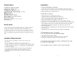
Capacity: 60 L @ 30˚C, 80% RH

Operating Relative Humidity Range: 

36%-90%

Amperage Usage:


6.82 Amps

Sound Level: 

60 dBa

Airflow @ 0.0” SP:250 

CFM

COP: 

2.7 L/kWh

Power Supply: 

115V/60Hz/Single Phase

Dimensions LxWxH: 

13.8” x 15.8” x 23.7”

Operating Temp. Range: 

33-105°F

Refrigerant: 

R410A

ETL Listed: 

Yes

Specifications

How


it


works

Installation Requirements

Abestorm dehumidifiers use an integrated humidistat to monitor the conditioned 

space. When the relative humidity goes above the selected setpoint, the 

dehumidifier will energize. Air is then drawn across an evaporator coil, which is 

cooler than the dew point of air. This means moisture will condense out of the air. 

The air is then reheated through the condenser coil and distributed back into the 

room.

If the unit is installed in a crawl space, all vents should be sealed. 

The


area


where


the


dehumidifier


is


located


should


be


sealed


with


a


vapor


barrier

For proper ventilation, neither the inlet or discharge should be positioned against 

a wall. The inlet needs a minimum of 12” clearance and the discharge requires a 

minimum of 36” clearance. 

Abestorm dehumidifiers are only intended for operation when the unit
is upright and level with the feet on the ground (unless using a Abestorm
Hanging Kit).

For the best air diffusion, install the unit so that a side panel faces the wall. 

Installation

•  

avoid putting it against a vapor barrier. Don’t use anything to support it at the base. 

Place it on the floor. If your device was place in any other position other than upright place 

it upright and allow two hours before turning it on.

1. 

Place your dehumidifier on a flat surface, 

•  

•  

Route the drain hose to a suitable drainage outside

There should not be any loops or dips on the drainage hose

2

.

Arrange the line of drainage

3. Recommended drain choice – PVC transition

Cut a ¾ OD PVC piece of cable, approximately 6inches long

•  

Seal of the point where the dehumidifier is located using a vapor barrier

•  

Seal off all openings if the unit is installed in a crawl space

•  

Avoid placing the inlet and outlet against a wall. This ensures proper ventilation. 

You need to give a 12’’ allowance of space with the inlet and 36’’ clearance for the discharge

•  

Place the side panel facing the wall so that the dehumidifier delivers the best diffusion

•  

Your dehumidifier is designed to be placed on the ground at the same level with 

the feet. Place it upright

•  

Your dehumidifier unit should always have a grounded connection with a GFCI protected 

15 amp electrical wire.

•  

Maintenance should be conducted with the power switched off or unplugged.

1. 

2. 

Insert the PVC that is cut into a ¾’’ elbow.

Attach the PVC and the elbow to a PVC drain measuring 3/4 inches long

3. Keep the PVC short. Keep the length of PVC as short as possible 

4. Insert the open side of the unit drain hose into a 6’’ PVCA piece so that it does 
not protrude into the elbow fitting

5. Your unit needs a slop of 1’’ for every 10 ‘’ run for it to get a correct flow

3

2

Summary of Contents for Living Environment CTR100

Page 1: ...User sManual Note as we keep upgrading our product we reserve the right to modify the product without natice in advance Abestorm Solutions INC Living Environment Series Add Berlin Tel 44 20 81243974 Email www abestorm com ...

Page 2: ...ber CTRH 100 Serial Number Date of Number For additional questions concerning your dehumidifier contact your local installer or call Abestorm at 44 20 81243974 Your dehumidifier should only be repaired by a qualified technician Always connect your dehumidifier using a grounded electrical connection as required for all electrical appliances The use of non grounded wiring will void the warranty Do n...

Page 3: ...barrier Don t use anything to support it at the base Place it on the floor If your device was place in any other position other than upright place it upright and allow two hours before turning it on 1 Place your dehumidifier on a flat surface Route the drain hose to a suitable drainage outside There should not be any loops or dips on the drainage hose 2 Arrange the line of drainage 3 Recommended d...

Page 4: ...will show E4 After a 1 minute delay the fan motor will turn off and the dehumidifier will not operate until the problem has been resolved Check to verify that the pump is functioning then unplug the unit for two minutes to reset the error code 5 Pump Trouble Warning Indicator Lights The display screen has two functions 1 Humidity Display Screen 1 When the unit is powered on it shows the humidity o...

Page 5: ...er is being utilized 4 Temperature The T button changes the temperature reading on your remote The remote comes from the factory in Celsius Press this button once to switch to Fahrenheit 5 Continuous Press this button to switch the unit into continuous mode CONT will appear on the display screen 6 Drain Pump Use this button if the unit will not be used for an extended period of time This button wi...

Page 6: ...oap 3 For MERV 10 HEPA Carbon Filters a Replace as necessary we recommend checking the filters at least 1x year Electrical Access Remove the screw on the control board cover Unscrew the 13 screws on the side panel Removing the Pump 1 2 3 4 Remove the 9 screws on the side panel and set panel aside Remove the screw holding the pump in place Undo the 3 pump electrical quick connects and 1 drain quick...

Page 7: ...e screw Wipe reservoir clean with a paper towel 4 Reassemble pump 5 Mix a 16 ounce solution of bleach 1 oz bleach 15 oz water OR vinegar 4 oz white vinegar 12 oz water 6 Pour the cleaning solution into the drain tray at the base of the coils If any cleaning solution gets on the coils flush with water 7 Allow solution to soak for 15 minutes 8 Reconnect the dehumidifier to power 9 Fill the reservoir...

Page 8: ... CaТ 5 Port Internal Cable N 1204 Supply Duict Collar Assembly Compressor Compressor Capacitor Coil Assembly Hot Gas Valve Assembly W 100 W 101 W 102 Remote Control Assembly includes W 101 and W 102 Remote Control Remote Control Cable Remote Control N 803 Condensate Pump Assembly N 105 AirWerx Remote Control Troubleshooting Display is Blank NoAirflow Error Code E1 Error Code E4 Error Code LO Error...

Page 9: ... an RA Return Authorization number 44 20 81243974 3 After you have been issued with your RA the customer is the one to take the unit to a certified technician repair center If the customer is unable to arrange for the same Abestorm will arrange for shipping at the expense of the customer 4 Once the unit is received BY Abestorm an inspection will be done If the results show that the warranty is inv...

Reviews: