background image

S1 Service manual   

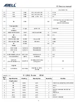
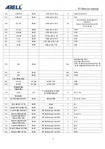
 18

76 

LQG15HN6N8J02  

MLK1005S6N8J 

0402 

HF Multi-layer inductor 

L14 

77 

LQG15HN18NJ02 

0402 

HF Multi-layer inductor 

L10   

78 

LGQ18HN22NJ00 

0603 

HF Multi-layer inductor 

L23 

79 

LQG15HN22NJ02D  

MLK1005S22NJ 

0402 

HF Multi-layer inductor 

L15 

80 

LQG15HN39NJ02D  

MLK1005S39NJ00D  

0402 

HF Multi-layer inductor 

L16 L34 

81 

LQG15HNR12J00D 

0402 

HF Multi-layer conductor 

R110 

82 NLV25T-R22J-PF  2520 

Wired 

conductor 

1  L22 

83 NLV25T-1R0T-PF  2520 

Wired 

conductor 

1  L18 

84 NLV25T-2R2T-PF  2520 

Wired 

conductor 

1  L12 

85 

MLF1608A3R3KT000 

0603 

LF Multi-layer conductor 

L28 

86 

MLF1608A4R7KT 

0603 

LF Multi-layer conductor 

L1 

87 0.3×1.5×2.5T  P 

type 

AIR-CORE COIL with 

pin“E" 

L2 L21 L24 L25 L26 L27 L33 

88 0.3×1.5×3.5T  P 

type 

AIR-CORE COIL with 

pin“E" 

L3 L4 L30 L31 

89 0.3×1.5×5.5T  P 

type 

AIR-CORE COIL with 

pin“E"" 

1 L13 


90 0.3×1.5×6.5T  P 

type 

AIR-CORE COIL with pin 

“E" 

1 L19 


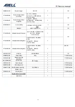
Diode 


91 

HSC277 

SOD-523 

DIODE 

D4 D5 D6 D8 

92 HVC131TRF SOD-523 

DIODE 

1 D12 

93 

HVC350B 

SOD-523 

Varactor Diode 

VD1 VD3 D3 D13 D14 

94 1SV214 SOD-323-A 

Varactor 

Diode 

VD2 

95 

MA2S11100L 

SOD-523 

DIODE 

D2 D9 D10 D11 

96 NC  D0402 


 NC 

D7 


Triode 


97 FMMT717  SOT-23  TRANSISTOR 

Q13 

98 2SC1623  SOT-23  TRANSISTOR 

Q7 

99 2SC2714  SOT-23  TRANSISTOR 

Q23 

100 2SC4226(R24)  SOT-323 

TRANSISTOR 

2  Q10 

Q14 

101 2SC4738-GR  SOT-416 

TRANSISTOR 

1 Q20 

102 2SC5066  SOT-323  TRANSISTOR 

Q8 

103 2SC5108  SOT-416  TRANSISTOR 

Q9 

104 2SK3078 SOT-89-3L 

FET 

Q18 

105 2SK3476  2-5N1A 

FET 

Q29 

106 

DTA123JE 

SOT-416 

TRANSISTOR 

Q1 Q3 Q11 

107 DTC114EE  SOT-416  TRANSISTOR 

1 Q6 

108 DTC144EE  SOT-416  TRANSISTOR 

1 Q4 

Summary of Contents for S1

Page 1: ...S1 Service manual 1 S1 SERVICE MANUAL V 1 ABELL INDUSTRIES CO LTD TEL 86 755 26521000 FAX 86 755 26404666 Email sales abell com cn Web www abell com cn ...

Page 2: ...manual 2 ABELL Industries Co Ltd S 1 SERVICE MANUAL V 1 Contents GENERAL 3 REALIGNMENT 4 DISASSEMBLE FOR REPAIR 6 CIRCUIT DESCRIPTION 9 PARTS LIST 14 SCHEMATIC DIAGRAM 36 PACKING 37 ADJUSTMENT 38 SPECIFICATIONS 43 ...

Page 3: ...es to all parts components kits or chassis If the part number is not known include the chassis or kit number of which it is a part and a sufficient description of the required component for proper identification PERSONAL SAFETY The following precautions are recommended for personal safety DO NOT transmit until all RF connectors are verified secure and any open connectors are properly terminated SH...

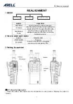
Page 4: ...e Use this mode to realign the various settings through the RS 232C port during manufacture work 2 How to enter each mode MODE PROCEDURE USER MODE Power on PC MODE Connect to the IBM PC compatible machine and controlled by FPU 3 Setting Acquainted PTT Push To Talk switch Press this switch then speak into the microphone to call a station Release the switch to receive User Mode PC Mode Manufacture M...

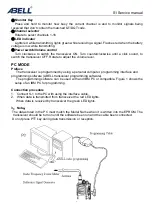
Page 5: ...lume level PC MODE Preface The transceiver is programmed by using a personal computer programming interface and programming software ABELL transceiver programming software The programming software can be used with and IBM PC or compatible Figure 1 shows the setup of an IBM PC for programming Connection procedure 1 Connect S 1 to the PC with using the interface cable 2 When data is transmitted from...

Page 6: ...eiver from the PC the destination data basic radio information for each set can be modified Normally it is not necessary to determined automatically when the frequency range frequency type is set The values should be modified only if necessary Data can be programmed into the EEPROM in RS 232C format data via the SP MIC plug In this mode the PTT line operates as TXD and RXD data lines respectively ...

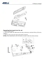
Page 7: ...Remove 8 pcs screw 2 Remove the solder from antenna terminal using a soldering iron and then lift the unit from the chassis 3 Remove 2 pcs screw and remove the antenna connector NOTE When reassembly the unit to the chassis be sure to solder the antenna terminal ...

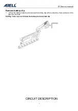
Page 8: ... 8 Remove battery clip 1 Lift up the battery metal reed and press the battery clip at the same time then remove it in the direction of arrow NOTE To be sure not broken the battery lock and belt clip CIRCUIT DESCRIPTION ...

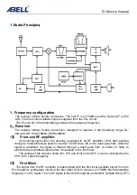
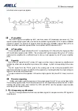
Page 9: ...RF amplifier Q12 after passing through a transmit receive switch circuit D7 and D8 are off and a band pass filter After the signal is amplified the signal is filtered through a band pass filter a triode LC filter to eliminate the unwanted signal before it is passed to the first mixer The voltage of the varactor diode D3 D13 and D14 on the AFC circuit is controlled by the CPU IC5 center frequency 2...

Page 10: ...he AF signal from IC7 enters IC7 again and the noise component is amplified and rectified by a filter and an amplifier to produce a DC voltage by Q20 corresponding to the noise level The DC signal from the FM IC goes to the analog port of the microprocessor IC5 IC51 determines whether to output sounds from the speaker by checking whether the input voltage is higher or lower than the preset value T...

Page 11: ...r is set low in receive mode 3 UNLOCK DETECTOR If a pulse signal appears at the CP1 pin of IC4 an unlocked condition occurs the voltage applied to the LOCK pin of the microprocessor to go low When the microprocessor detects this condition the transmitter and receiver are disabled and the error indicating alarm occurs ignoring the push to talk switch input signal 4 Transmitter 1 Transmit audio The ...

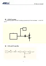
Page 12: ...S1 Service manual 12 2 QT DQT encoder A necessary signal for QT DQT encoding is generated by IC5 and modulated at the VCO and X1 3 VCO and RF amplifier IC5 C142 VD2 X1 ...

Page 13: ... to the antenna terminal The transmit receive switching circuit is comprised of D17 and D17 turned on conductive in transmit mode and off isolated in receive mode 5 Power supply A 3 7V reference power supply for the control circuit is derived from an internal battery 1000mAh Li ion by IC3 This reference supply VDD is 3V which is used to provide a 3V supply in transmit mode TXC a 3V supply in recei...

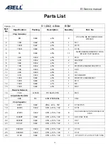
Page 14: ... 1 C93 11 22K 0402 5 1 C3 12 47K 0402 5 3 R23 R43 R70 13 100K 0402 5 6 R6 R7 R14 R24 R44 R47 120K 0402 1 1 R10 14 150K 0402 1 1 R9 15 150K 0402 5 1 R22 Resistor Network 16 1K 4 4 0603 YC164 JR 071K 1 R45 Adjustable Resistor 17 68K Φ3 EVM3YSX50BS4 1 VR2 Chip Capacitor 18 22PF 0402 COG 5 16V 2 C134 C135 19 220PF 0402 X7R 10 16V 1 C151 20 470PF 0402 X7R 10 16V 8 C22 C23 C24 C25 C128 C166 C167 C183 21...

Page 15: ...0603 NC D1 Triode 37 DTC114EE SOT 416 TRANSISTOR 1 Q17 38 DTC114TE SOT 416 TRANSISTOR 1 Q16 IC 39 S 80128ANMC JCN T2 SOT 23 5 Restoration IC 1 IC2 40 AT24C08BN SH SOP8 EEPROM 1 IC1 41 SRT3210 CS 331DF98B V1 2 SSOP100 IC320QUAD100 after writing CPU 1 IC5 Crystal 42 32 768KHz 8 0 3 8mm CM200C 12 5PF 30PPM 1 Y1 Version 1 0 S1 D02 B side BOM Ref No Specification Packing Description Quantity Part No Ch...

Page 16: ...02 5 6 R39 R64 R73 R97 R141 R142 27 120K 0402 5 1 R8 28 150K 0402 5 1 C139 29 220K 0402 5 1 R104 30 270K 0402 5 1 R63 31 330K 0402 5 1 R98 32 680K 0402 5 1 R65 Resistor Network 33 1K 4 4 0603 YC164 JR 071K 1 R132 Chip Capacitor 34 0 5PF 0402 COG 0 1PF 16V 1 C173 35 0 75PF 0402 COG 0 1PF 16V 2 C39 C57 36 1PF 0402 COG 0 1PF 16V 1 C159 37 1PF 0603 COG 0 1PF 16V 2 C86 C119 38 2PF 0402 COG 0 1PF 16V 5 ...

Page 17: ...C31 C34 C146 C180 59 0 047UF 0402 X7R 10 16V 1 C97 60 0 1UF 0402 X7R 10 16V 15 C5 C10 C16 C18 C20 C21 C30 C41 C95 C102 C103 C104 C117 C123 C132 61 0 1UF 0805 X7R 10 16V 1 C175 62 0 33UF 0603 X7R 10 16V 1 C181 63 0 47UF 0402 X5R 10 6 3V 1 C178 64 1UF 0402 Y5V 80 20 10V 1 C33 65 1UF 0805 Y5V 80 20 16V 1 C107 66 10UF 0805 X5R 10 10V 1 C26 67 NC 0805 NC C143 68 NC 0603 NC RTH1 69 NC 0402 NC C8 C68 C69...

Page 18: ...2 L21 L24 L25 L26 L27 L33 88 0 3 1 5 3 5T P type AIR CORE COIL with pin E 4 L3 L4 L30 L31 89 0 3 1 5 5 5T P type AIR CORE COIL with pin E 1 L13 90 0 3 1 5 6 5T P type AIR CORE COIL with pin E 1 L19 Diode 91 HSC277 SOD 523 DIODE 4 D4 D5 D6 D8 92 HVC131TRF SOD 523 DIODE 1 D12 93 HVC350B SOD 523 Varactor Diode 5 VD1 VD3 D3 D13 D14 94 1SV214 SOD 323 A Varactor Diode 1 VD2 95 MA2S11100L SOD 523 DIODE 4...

Page 19: ...uantity Part No Chip Resistor 1 0R 0402 5 9 C55 C153 R4 R15 R25 R30 R31 R74 R85 2 10R 0402 5 1 R11 3 100R 0402 5 1 R116 4 150R 0402 5 1 C136 5 1K 0402 5 11 R2 R19 R26 R48 R49 R101 R106 R114 R115 R134 R136 6 2 2K 0402 5 1 R18 7 4 7K 0402 5 2 R82 R121 8 5 6K 0402 5 1 R3 9 10K 0402 5 7 R1 R5 R32 R40 R41 R92 R118 10 15K 0402 5 1 C93 11 22K 0402 5 1 C3 12 47K 0402 5 3 R23 R43 R70 13 100K 0402 5 7 R6 R7...

Page 20: ...05 X5R 10 10V 1 C4 30 NC 0402 NC C49 C54 C61 C90 C94 C163 C191 R46 R57 R72 R108 R109 Tan Capacitor 31 1UF A 型 20 16V 2 C99 C142 Inductor 32 BLM18AG601SN1D 0603 0603 Bead 600R 2 L6 L32 33 NC 1010 NC L5 Diode 34 LED 02 0603 QGC D0603 Green LED 1 LED3 35 LED 02 0603 QRC D0603 Red LED 1 LED4 36 NC D0603 NC D1 Triode 37 DTC114EE SOT 416 TRANSISTOR 1 Q17 38 DTC114TE SOT 416 TRANSISTOR 1 Q16 IC 39 PST912...

Page 21: ...02 5 1 R135 16 3 3K 0402 5 3 R58 R75 R95 17 4 7K 0402 5 5 R17 R52 R68 R78 R113 18 6 8K 0402 5 2 R51 R76 19 8 2K 0402 5 6 R21 R38 R61 R66 R69 R83 20 10K 0402 5 3 R62 R79 R123 21 12K 0402 5 1 R88 22 22K 0402 5 1 R129 23 47K 0402 5 6 R36 R56 R59 R89 R91 R133 24 68K 0402 5 1 R103 25 82K 0402 5 2 R90 R138 26 100K 0402 5 6 R39 R64 R73 R97 R141 R142 27 120K 0402 5 1 R8 28 150K 0402 5 1 C139 29 220K 0402 ...

Page 22: ... 5 16V 2 C138 C149 54 100PF 0402 COG 5 16V 5 C108 C127 C158 C168 C169 55 470PF 0402 X7R 10 16V 15 C32 C51 C52 C79 C81 C110 C111 C122 C126 C144 C155 C160 C171 C172 C177 56 1000PF 0402 X7R 10 16V 17 C28 C29 C35 C42 C43 C44 C45 C46 C47 C48 C83 C84 C92 C105 C147 C157 C165 57 1000PF 0603 X7R 10 16V 1 C148 58 0 01UF 0402 X7R 10 16V 4 C31 C34 C146 C180 59 0 047UF 0402 X7R 10 16V 1 C97 60 0 1UF 0402 X7R 1...

Page 23: ... 2R2T PF 2520 Wired inductor 1 L12 84 MLF1608A3R3KT000 0603 LF Multi Layer inductor 1 L28 85 MLF1608A4R7KT 0603 LF Multi Layer inductor 1 L1 86 0 3 1 5 2 5T P 型 AIR CORE COIL with pin E 7 L2 L21 L24 L25 L26 L27 L33 87 0 3 1 5 3 5T P 型 AIR CORE COIL with pin E 4 L3 L4 L30 L31 88 0 3 1 5 4 5T P 型 AIR CORE COIL with pin E 1 L13 89 0 3 1 5 6 5T P 型 AIR CORE COIL with pin E 1 L19 Diode 90 HSC277 SOD 52...

Page 24: ...35SA 1 X1 114 PCB TH308K V03 PSW V3 0 V03 09 19 05 UHF 1 S1 446MHz A Side BOM Ref NO Specification Packing Description Quantity Part No Chip Resistor 1 0R 0402 5 10 C55 C153 R4 R15 R25 R31 R48 R74 R85 R121 2 10R 0402 5 1 R11 3 100R 0402 5 1 R116 4 150R 0402 5 1 C136 5 1K 0402 5 10 R2 R19 R26 R49 R101 R106 R114 R 115 R134 R136 6 2 2K 0402 5 1 R18 7 4 7K 0402 5 1 R82 8 5 6K 0402 5 1 R3 9 10K 0402 5 ...

Page 25: ...C7 C9 C11 C12 C14 C15 C17 C53 C60 C85 C150 C194 C195 28 1UF 0402 X5R 10 10V 1 C164 29 1UF 0603 Y5V 80 20 16V 1 C182 30 10UF 0805 X5R 10 10V 1 C4 31 NC 0402 NC C19 C54 C61 C90 C94 C163 R46 R57 R72 R108 R109 Tan capacitor 32 1UF A type 20 16V 2 C99 C142 Inductor 33 BLM18AG601SN1D 0603 0603 Bead 600R 2 L6 L32 34 NC 1010 NC L5 Diode 35 LED 02 0603 QGC D0603 Green LED 1 LED3 36 LED 02 0603 QRC D0603 Re...

Page 26: ... 7 100R 0402 5 4 R16 R71 R86 R87 8 150R 0402 5 1 R105 9 220R 0402 5 3 R80 R81 R139 10 270R 0402 5 2 R54 R67 11 820R 0402 5 1 R28 12 1K 0402 5 4 R53 R55 R107 R122 13 1 2K 0402 5 2 R50 R99 14 2K 0402 5 1 R95 15 2 2K 0402 5 5 R29 R37 R60 R77 R125 16 2 7K 0402 5 1 R135 17 3 3K 0402 5 3 R20 R58 R75 18 4 7K 0402 5 5 R17 R52 R68 R78 R113 19 6 8K 0402 5 2 R51 R76 20 8 2K 0402 5 6 R21 R38 R61 R66 R69 R83 2...

Page 27: ...74 40 3PF 0603 COG 0 1PF 16V 1 C72 41 4PF 0402 COG 0 1PF 16V 4 C64 C67 C75 C156 42 5PF 0402 COG 0 1PF 16V 4 C38 C40 C76 C77 43 6PF 0402 COG 0 25PF 16V 2 C36 C65 44 7PF 0402 COG 0 5PF 16V 2 C70 C125 45 10PF 0402 COG 5 16V 4 C6 C114 C115 C162 46 15PF 0402 COG 5 16V 1 C116 47 18PF 0603 COG 5 16V 1 C78 48 20PF 0402 COG 5 16V 1 C50 49 27PF 0603 COG 5 16V 1 C71 50 30PF 0402 COG 5 16V 3 C121 C138 C149 51...

Page 28: ...NC RTH1 67 NC 0805 NC C143 Tan Capacitor 68 2 2UF A Type 20 10V 1 C98 69 100UF B Type 20 6 3V 1 C196 Adjustable Capacitor 70 6PF φ3 TZC3Z060A110R00 ECRKN006A61X 2 TC1 TC2 Inductor 71 BLM18AG601SN1D 0603 Bead 600R 4 L7 L8 L11 L29 72 MGLB2012 011B 0805 Bead 1 L9 73 BLM21PG300SN1DS 0805 Bead 1 L35 74 LQG15HN2N2S02D 0402 HF Multi Layer Inductor 1 L17 75 LQG15HS8N2J02D 0402 HF Multi Layer Inductor 2 L1...

Page 29: ...D13 D14 93 1SV214 SOD 323 A Varactor diode 1 VD2 94 MA2S11100L SOD 523 DIODE 4 D2 D9 D10 D11 95 NC D0402 NC D7 Tiode 96 FMMT717 SOT 23 TRANSISTOR 1 Q13 97 2SC1623 SOT 23 TRANSISTOR 1 Q7 98 2SC2714 SOT 23 TRANSISTOR 1 Q23 99 2SC4226 SOT 323 TRANSISTOR 2 Q10 Q14 100 2SC4738 GR SOT 416 TRANSISTOR 1 Q20 101 2SC5066 SOT 323 TRANSISTOR 1 Q8 102 2SC5108 SOT 416 TRANSISTOR 1 Q9 103 2SK3078 SOT 89 3L FET 1...

Page 30: ...4308 002 LED PC Transparence 1 LED TH308 Series Rubber parts L01308 006 PTT rubber button Rubber 1 TH308 Series L02308 003 Speaker Rubber mat Rubber 1 TH308 Series L02308 016 PTT rubber mat 8 5 3 0mm 1 TH308 Series Single sided glue S07308 008 Speaker dustproof vover φ46 5 35 7 8mm 1 N 250 Import from USA TH308 Series S02307 001 Speaker sponge cushion φ16 1 mm 1 TH308 Series S02307 003 Crystal spo...

Page 31: ...90 003 Nut M09701 Φ9 0 2 4 1 Match power switch M19012 001 Nut Φ12 5 2 5 M9 1 Brass color match antenna seat M19035 004 Nut Φ3 5 3 0 M2 5 2 Brass color assembled on the housing TH308FB H FC A82 M18308 002 Belt clip spring 1 TH308 series M02308 002 Belt clip spindle Φ1 9 19 5 1 TH308G 308FB M18308 006 Belt clip spring block 1 TH308 series A02307 002 Antenna seat SMA JFD 13 new 1 Coax connector Labl...

Page 32: ... 7 12 4mm 1 T14308 028 Adaptor label English Input 100 240 50 60Hz 0 2A Output 5V 500mA 15 7 12 4mm 1 S1 T14308 030 Adaptor lable English Input 100 240 50 60Hz 0 2A Output 5V 500mA 29 8 16 8mm 1 A20 S1 A01D02 007 antenna 400 420MHZ 1 S1 B09308 001 Hand strap blue 1 TH308 series B12308 002 Plastic belt clip assembly 1 TH308 series B11A308 084 Radio unit S1 D02 1 B01308 012 User manual 1 TH308 serie...

Page 33: ...K D9 MA2S11100L D4 HSC277 1 1 2 2 C120 10UF R127 22R PLV R7 100K R57 NC R60 2 2K R59 47K R55 1K VD2 ISV214 VD1 HVC350B R56 47K R54 270R R122 1K R29 2 2K R125 2 2K C98 2 2uF CF2 450HT R95 3 3K R53 1K L3 0 3 1 5 3 5T L4 0 3 1 5 3 5T C108 100P C106 NC D10 MA2S11100L R103 68K C107 1uF R129 22K C47 1000P L18 1uH C67 4P L9 瓷珠 R89 47K F2 JT BM450 C49 C96 NC Q18 2SK3078 C124 0 1uF R48 1K Q16 DTC114TE R87 ...

Page 34: ...S1 Service manual 34 A Side ...

Page 35: ...S1 Service manual 35 B Side ...

Page 36: ...S1 Service manual 36 Explored view ...

Page 37: ... H25 0085 04 14 PACKING FIXTURE H12 3037 02 21 BELT HOOK J29 0624 03 16 PROTECTION BAG H25 2012 04 3 CAP B09 0351 03 20 SP MIC HOLDER J21 4493 04 17 ITEM CARTON CASE H52 1522 02 G SCREW SET N99 0396 05 ANT WHIP ANTENNA T90 0694 15 M T90 0684 05 M4 ...

Page 38: ...o 500MHz or blow and measurements are highly stable and accurate about 0 2ppm 4 Power Meter 1 Measurable frequency Up to 500MHz 2 Impedance 50Ω instability 3 Measuring range full scare of 5W or so 4 A standard cable 5D2W 1m must be used 5 RF Voltmeter RF V M 1 Frequency range up to 500MHz or so 6 Linear Detector 1 Frequency range up to 500MHz or so 2 Characteristics are flat CN is 60dB or more 7 D...

Page 39: ...00KHz 2 Input level 50mV to10Vrms 3 ADJUSTMENT FREQUENCY LIST Destination DH DL PMR446 Channel TX MHz RX MHz TX MHz RX MHz TX MHz RX MHz Centre 460 050 410 05 446 00 Low 450 050 400 05 446 05 High 469 950 419 95 446 10 Remark Connect the transceiver to the PC Send the channel data to the transceiver then backup the data Program the adjustment frequencies which are on the list into the transceiver ...

Page 40: ...ation Battery level Section common to the transmitter and receiver VCO Measurement Adjustment Item Condition Test Equipment Terminal Parts Method Specification Remarks 1 Setting 1 Power supply voltage Battery terminal 4V 1 CH TX high 2 2V 0 2V 2 CH RX high 2 2V 0 2 V 3 CH TX low 4 CH RX low Test Higher than 1 0V 2 VCO lock voltage 5 PMR446 Digital voltmeter Tp5 L13 1 2V 0 2 V Receiver section Item...

Page 41: ...ter CH RX LOW CH RX HIGH SSG output 116dBm 0 35µV MOD 1KHz DEV 3 0KHz wide 1 5KHz narrow test SINAD 12dB or more 1 CH RX Centre MONI open 2 level 5 SSG output 123dBm level 5 to close the squelch Squelch must be off 4 Squelch Level PC mode SSG Oscillosco pe AF V M Distortion meter Antenna Speaker PC mode Transmitter section Measurement Adjustment Item Condition Test equipment Terminal Parts Method ...

Page 42: ... W 1 1KHz 1 8KHz N 5 QT DEV PC MODE 1 Test channel CH02 centre frequency Modulation Analyzer or linear detector LPF 3kHz Oscilloscope Audio generator Audio voltmeter Antenna Adjust to 0 65 KHz W Adjust to 0 35 KHz N 150Hz 6 DQT DEV PC MODE Test channel CH03 DQT023N Modulation Analyzer or linear detector LPF 3kHz Oscilloscope Audio generator Audio voltmeter antenna Adjust to 0 65 KHz W Adjust to 0 ...

Page 43: ...y range 450 470MHz DH 400 420MHz DL 446 446 1 MHz PMR446 RF output power 1W Channel capacity 16 Voltage 4V DC 20 Temperature 30 60 22 140 With AB L105C 3 7V 1000mAh battery Dimension and weight 58 2 5 16 W 125 5 4 15 16 H 35 1 3 8 L mm inch 158g ...

Reviews: