


32
• This operation must be carried out by ABB personnel or
by suitably qualified customer personnel with in-depth
knowledge of the apparatus (IEC 62271-1, par. 10.4.2.).
• Always check that the apparatus is in the open position
before carrying out any activities.
Check that the medium voltage and auxiliary power supplies
have been removed.
Maintenance of the apparatus must only be carried out with
the contactor de-energized, racked-out of the compartment
of the enclosure and with the capacitor of the auxiliary
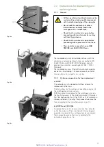
circuit discharged. To discharge the capacitor, remove
power from the -XDB10 terminal box and connect the
mobile two-pole -XDB50 connector to the ABB type CFD
device (fig. 13c). Completion of discharging is signalled by
the red light going completely off.
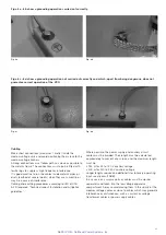
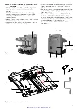
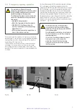
• The auxiliary circuit can be configured for all the direct and
alternating current voltages within the reference range. To
change the voltage value defined during the ordering stage,
proceed as follows: 1) remove the rear plastic protection
(fig. 13a); 2) access the MAC R2 electronic card (fig. 13b);
3) prepare the dip-switches according to the indications
given on the last page of the electric circuit diagram.
• After having set the desired value, the label with the new
voltage value must be overlayed the front rating plate of the
contactor.
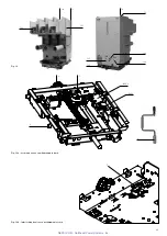
Fig. 13a
Fig. 13b
Fig. 13c
Fig. 13d
• The small plate with the correct voltage value is in the
document envelope accompanying the product, along with
the electric circuit diagram and this manual.
• Contactor functional check is mandatory after the new
voltage setting; the qualified customer’s personnel should
carry out this check, responsibility for the interventions lies
with the customer.
5.7.2.1 Changing the supply voltage of the contactor
(within the reference range)
NEPSI.COM - Northeast Power Systems. Inc.


