background image

 Incastro

7

8

3

3

2

3

3

2

3

1

2

6

5

4

21

D I S T R I B U T I O N  S O LU T I O N S

(tighten all the screws)

(Fit the roof in 
place)

Upper cover panel

DY800/316 panel

End panel fixing points

Front panel

Upper cover panel

Tighten all the screws

Tighten the
end plate
screws

(Tighten all the 
screws)

Position the 
roof

Slot-in joint

Summary of Contents for UniSec DY800

Page 1: ...tions for the operating sequence of all UniSec DY800 cubicles 12 7 Voltage and phase correspondence indicator 13 8 Installation 14 9 Cable test 24 10 Putting into service 25 11 Routine inspections 26 12 Quality of the products and environmental protection 27 13 SF6 gas 28 Installation service and maintenance instructions for 24 kV prefabricated assemblies with arc proof metal enclosures and multi ...

Page 2: ...are carried out by qualified personnel with suitable knowledge of the apparatus To ensure that the installations are built in accordance with the rules of good working practice and safety in the work place make sure that the regulatory and legal requirements are complied with during installation putting into service and maintenance The personnel who access the switchgear must possess PES or PEI qu...

Page 3: ...he ground so that the overall height is 4 m maximum The surface of the loading platform must be non slip with a high coefficient of friction The assemblies must be arranged cross wise and back to back on the platform with suitable material in between so as to prevent them from touching and pressing against each other Frame members must be arranged on the platform so as to space out the units and p...

Page 4: ... goods fail to correspond immediately inform ABB either directly or through your representative or supplier and the haulage contractor that made the delivery The cubicles are supplied solely with the accessories specified at the time of order and validated in the order confirmation The following items are to be found inside the cubicles instruction manual a packet containing screws nuts washers bu...

Page 5: ...on when using a lift truck for handling purposes UniSec switchgear is normally placed on a wooden pallet and fastened with four bolts one per corner For handling purposes the switchgear can be lifted by crane using ropes with snap hooks conforming to the safety standards inserted through the eyebolts on the top of the units or by fork lift truck In this case the forks must be inserted at the sides...

Page 6: ...30 A Admissible rated short time withstand current 16 kA Electrical life class ref IEC 62271 100 E2 Admissible short time peak current value 40 kA Rated short circuit duration 1 s Rated short circuit breaking capacity 16 kA Rated operating sequence O 0 3 sec CO 30 sec CO Mechanical life 10000 operations Class M2 Rated breaking current values circuit mainly active 630 A vacuum transformer 6 3 A no ...

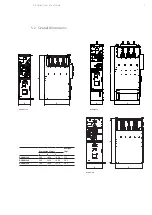
Page 7: ...C A C B A C B 7 DISTRIBUTION SOLUTIONS 5 2 Overall dimensions DY800 116 DY800 216 DY800 316 Dimensions mm Weight kg A B C DY800 116 500 1850 1050 275 DY800 216 500 2250 1050 302 DY800 316 700 1950 1150 305 ...

Page 8: ...aratus with 3 positions and circuit breaker small size low amount of SF6 used for insulation ease of use All the cubicles are internal arc proof in accordance with the provisions established by standard IEC 62271 200 The IAC classification of the various types restricted to authorized persons alone class A complies with the 5 criteria established by the standard The 3 types of UniSec DY800 cubicle...

Page 9: ...5 3 5 Characteristics of the circuit breaker operating mechanism The circuit breaker is equipped with a three pole operating mechanism with the following circuits and devices a three pole voltage start up closing circuit a three pole voltage start up opening circuit an anti pumping device to prevent further closings other than the first when opening occurs during the initial closing request This d...

Page 10: ...ector SL in the open position and earthing switch ST in the closed position both with moving contacts locked at end stop This interlock is created electrically by cutting off the electrical controls of circuit breaker I 4 It must only be possible to open the cubicle door in conditions of safety i e with feeder disconnector SL open and earthing switch ST closed This condition is obtained with a pad...

Page 11: ... lever is in the lever seat of earthing switch ST Insertion of the operating lever acts on a micro switch which cuts off the power supplied to the control circuits of circuit breaker I 5 5 5 Interlock between feeder disconnector SL and circuit breaker I This is a mechanical lock of the inhibiting type that prevents the operating lever of feeder disconnector SL from being inserted into its seat if ...

Page 12: ...between the disconnector and circuit breaker in the upward direction Fully insert the operating lever into its seat 10 in earthing switch ST Turn the operating lever clockwise until the operation has been completed Remove the operating lever Check that the indicator 9 confirms that closing has occurred by displaying letter I in black on a yellow background 4 Open the door by pulling the handle up ...

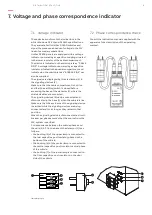
Page 13: ... earthing switch is closed before accessing the base of the detector 1 where the shielded cables are connected The signaling devices 2 can be connected and disconnected in the base 1 when the cubicle is live Make sure that the enclosure of the signaling device is earthed while the signaling devices are being connected and for as long as they remain in that position When the signaling device is dis...

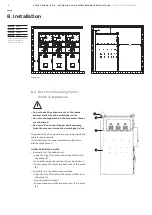
Page 14: ...away from the area overlooking the fumes exhaust stacks and do not install apparatus in that area Maximum ambient air temperature 40 C Minimum ambient air temperature 15 C Relative humidity 95 without condensation Altitude 1000 m Comply with the indications in the product standards if other installation conditions are involved Please consult us for special installation requirements The areas throu...

Page 15: ...TION SOLUTIONS DY800 216 A mm 450 B mm 100 C mm 1200 D mm 100 Dimension C represents the space required to withdraw the cubicle A mm B mm C mm 1200 D mm 100 Dimension C represents the space required to withdraw the cubicle DY800 116 ...

Page 16: ...n electric arc occurring inside the cubicle is very remote If it should occur proceed as described below to eliminate the fumes UniSec DY800 116 and 216 Internal arc in the busbar duct open the flap 1 to allow the fumes to flow into the stack 2 the cable compartment flap 3 remains closed fumes escape from the exhaust vent of the stack 4 Internal arc in the cable compartment open the flap 3 to allo...

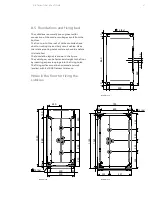
Page 17: ...for connection of the medium voltage circuit from the bottom The front part of the roof of UniSec cubicles has a duct for routing the auxiliary circuit cables Make the relative routing holes under each cubicle before it is installed The foundation layout is shown in the figure The switchgear can be fastened straight to the floor by inserting expansion plugs into the fixing holes The fixing surface...

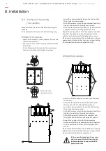
Page 18: ...ghtening them move the second cubicle close to the first so that their sides touch each other fit the M4 screws into the holes marked X and fully tighten the bolts into the adjacent cubicle fit the M10 screws into the holes marked Y and fully tighten the bolts into the adjacent cubicle Repeat these operations for the successive cubicles and after they have been joined together fix the cubicles to ...

Page 19: ...tion is horizontal and well leveled with 2 1000 maximum flatness 2 mm with respect to a square meter place the base in the substation 20 mm from the right hand wall and 190 mm from the rear wall and mark the positions of the holes drill the floor insert 4 expansion plugs and fix the base in place Make sure that the cable outlet 2 in the base is on the left It the unit must be positioned in the lef...

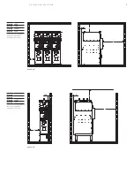
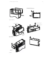
Page 20: ...20 UNISEC DY800 ED 4 ACCORDING TO E DISTRIBUZIONE SPECIFICATIONS INSTALL ATION MANUAL End panel Panel assembly sequence Comply with the numbered sequence in the figures below to assemble the panels DY800 116 panel Detail A Detail B View from above Clamps 8 Installation Slot in joint ...

Page 21: ...ON SOLUTIONS tighten all the screws Fit the roof in place Upper cover panel DY800 316 panel End panel fixing points Front panel Upper cover panel Tighten all the screws Tighten the end plate screws Tighten all the screws Position the roof Slot in joint ...

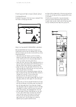
Page 22: ...g insulators is perfectly clean and degreased Repeat the operations described in the previous paragraph for the central phase detail D Make sure that the strip A is also connected Only couple the busbars for the remaining phases since the strips are already connected comply with the previously described procedure Tightening torque 60 Nm max 8 7 2 Earthing busbars The earthing busbar is routed long...

Page 23: ...ternal connection between the motor operated control and telecontrol extension unit is made with multicore cable equipped with flying connectors The figure below illustrates the route inside the cubicle of the cables that connect the current transformers the toroidal transformer for homopolar protection and the RG apparatus Cable route inside the cubicle Flexible metal tubes inside the cubicles al...

Page 24: ...g ensure that the part of the installation in which the work must be performed is in a safe condition Connection of cables for test purposes applied voltage and troubleshooting alters the characteristics of the switchgear Those who do this must ensure compliance with the correct procedures in order to guarantee safe conditions for the workers Obligatory conditions when performing voltage tests on ...

Page 25: ... and those included in the configuration have been installed correctly Make sure that all panels for protection against accidental contact have been installed correctly Check that the interlocks function correctly and that the keys if any are correctly joined with a welded ring if they are required for the interlocks Check that the mechanical operating mechanisms can be operated by applying 200 Nm...

Page 26: ...k along with the date description of the fault and reference data allowing the device to be identified see chap 2 Refer to article 11 of standard IEC 62271 1 if further details are required Do not hestitate to call us if problems arise It is always a good idea to inspect the apparatus screw and bolt tightness abnormal heating etc a few months after it has been put into service The following table ...

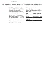
Page 27: ...own by Standard ISO 14001 ABB offers its skills and assistance to facilitate product recycling and disposal at the end of life stage Compliance with the local regulations when disposing of products is always mandatory 12 2 Disposal methods The products can be disposed of by means of heat treatments in incineration systems or by storage in dedicated areas Material Recommended disposal method Metals...

Page 28: ...ic If the overpressure valve fails due to events involving high arc energy levels persons must not enter the area before it has been subjected to intensive ventilation A suitable filter class FFP3 is required for filtering the nanoparticles during the cleaning and disassembly operations following failure of the overpressure valve due to high arc energy levels ...

Page 29: ...29 DISTRIBUTION SOLUTIONS Notes ...

Page 30: ...contactcenters More service information abb com service Copyright 2018 ABB All rights reserved The data and illustrations are not binding We reserve the right to make changes in the course of technical development of the product 1VCD601365 Rev A en Unisec DY800 Installation manual Ed 4 e Distribuzione 2018 09 mt ...

Reviews: