


1ZSC000562-AAZ en
|
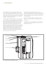
Installation and commissioning guide UCL/VUCL
21
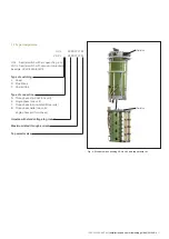
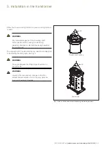
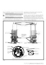
Fig. 13.
Cover
O-ring
Upper flange
O-ring
Lower flange
O-ring
Guide bar for
diverter switch
Flat washer
Spring washer
Screw
Locking device DS 4
Lifting eye for
diverter switch
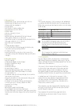
Bevel gear
Red mark
Position
indicator
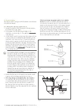
Fig. 12. Bevel gear.
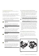
Oil drainage plug
Socket handle
Bottom valve key
DS16,
key width 10 mm
Oil drainage tube
Fig. 14.
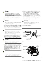
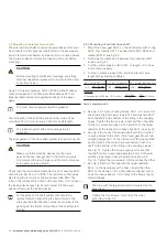
CAUTION
The drive shaft must not be rotated.
11. The guide bar for positioning the diverter switch in the
housing is secured in the upper flange with screws
and washers. Remove the screws and washers. Store
the guide bar in the diverter switch housing until it is
remounted. Save the screws and washers.
12. Remove the nuts and washers inside the upper flange and
remove the flange by lifting it by the lifting eyes. Store the
upper flange, and the O-ring at a dust-free location. Save
the nuts and washers.
13. The tap-changer is now ready for drying together with the
transformer. Follow the instructions in Chapter 4.
Summary of Contents for UCL
Page 1: ...On load tap changers type UCL and VUCL Installation and commissioning guide 1ZSC000562 AAZ en...
Page 8: ......
Page 53: ......
Page 54: ......
Page 55: ......