


16
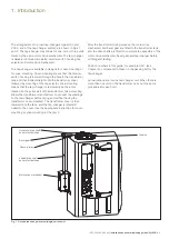
Installation and commissioning guide UCL/VUCL
|
1ZSC000562-AAZ en
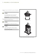
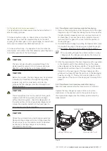
3.1 Cover-mounting
The diverter switch housing and the tap selector are delivered
in separate packaging.
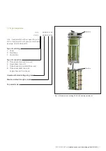
3.1.1 UCL/VUCL with tap selector size III
1. Unpack the diverter switch housing and the tap selector,
and remove the drying agent.
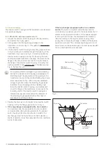
2. Fit the gasket into the tap-changer flange on the
transformer cover; see Fig. 6. (This gasket is not included
in the delivery.)
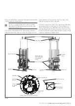
3. Lift the diverter switch housing by the lifting eyes as shown
in Fig. 4 and lower it carefully through the opening in the
transformer top cover; see Fig. 5. Correctly position the
diverter switch housing correctly for mounting the outer
shaft system (see transformer drawing). The studs on the
flange on the transformer cover shall fit into the holes in
the flange of the diverter switch housing. Fit twenty-four
washers and M12 nuts (not included
in the delivery); see
Fig. 6. Tighten the nuts.
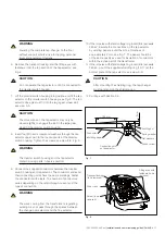
For impulse withstand voltages to ground exceeding
380 kV, the diverter switch housing is equipped with
shielding rings. The play between the opening in the
transformer cover and the middle shielding ring is very
small, especially for the 1050 kV impulse withstand
voltage to ground, where the shielding ring is paper
insulated. To avoid damage to the shielding rings,
lower the diverter switch housing very carefully and
cover the flange in the transformer cover next to the
insulating shaft of the diverter switch housing and
diametrically opposed area (where the diameter of
the shielding ring is greatest) with a thin sheet of
pressboard (or similar material).
4. Position the tap selector for joining to the diverter switch
housing. Lift by the lifting eyes as shown in Fig. 4.
5.
If the tap-changer is equipped with a tie-in resistor
for mounting under the tap selector, the tie-in resistor
is mounted after joining the tap selector to the diverter
switch housing. After mounting the tie-in resistor, the
tap-changer must not be set down so that it stands on
the tie-in resistor. It must be suspended from an overhead
crane, for example.
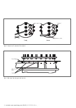
Fig. 5.
If the tap-changer is equipped with a tie-in resistor
switch
, the switch is mounted under the tap selector
upon delivery. A special support in the box ensures that it
stands on the tap selector bottom. If this special support
is removed from the box, the tap selector can stand on
this when joining to the diverter switch housing. After
joining, the complete tap-changer is lifted and the special
support is removed. The complete tap-changer must not
be set down on the special support. It must be suspended
from an overhead crane, for example.
Fig. 6.
Opening in
transformer cover
Tap selector
Diverter switch
Washer
(x24)
Stud (x24)
Nut M12 (x24)
Top cover
Top section
Gasket
Transformer
top cover
Summary of Contents for UCL
Page 1: ...On load tap changers type UCL and VUCL Installation and commissioning guide 1ZSC000562 AAZ en...
Page 8: ......
Page 53: ......
Page 54: ......
Page 55: ......