
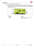


2-sensor input functionality / Dual sensor mode
OI/TTF300-EN TTF300
49
8.5
D/A analog output compensation (4 and 20 mA trim)
Output compensation is used to correct errors in the power input of the superordinate system.
Analog output compensation for the transmitter can be used to modify the loop current so that
the desired value is displayed in the superordinate system.
Error compensation for the superordinate system is possible at the LRL with 4 mA or 20 mA.
(Single point error correction: Offset or two-point error correction linear gradient)
D/A analog output compensation can be accessed in the HMI LCD display via the menu path
Calibrate / Analog Output / Trim 4/20mA or via TTF300 DTM via the path Device / Maintenance
/ Adjust.
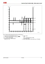
Prior to analog compensation, it is necessary to determine the loop current values based on
iterative entry of current data in simulation mode; the superordinate I/O system displays exactly
4,000 mA, the LRL or 20,000 mA and the URL temperature. The current loop values are to
measured via amperemeter and to record .
Simulate the LRL or 4,000 mA +/- 16µA in D/A analog output compensation mode using sensor
simulation. Thereafter, enter the iteratively measured current at which the superordinate system
displays exactly 4,000 mA or the LRL as adjustment value. Proceed in a similar manner for the
URL or 20,000 mA.
The disadvantage of D/A analog output compensation is that the HART signal prior to the D/A
conversion without correction differs from the analog output signal after D/A conversion due to
the incoming error correction of the superordinate system. As a result, the HART value
displayed is slightly different from the output signal current.
8.6
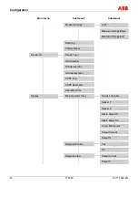
HART variable assignment
Because every HART devices can basically transmit four variables, the measurement value to
be transmitted via HART signal can be specified in the menu Device / Configuration when using
the TTF300 DTM or EDD for device setup.
The primary variable is mapped to the 4 … 20 mA output as well as the secondary, tertiary and
quaternary variables.
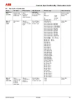
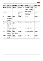
The following values can be assigned to variables:
-
Elec. input 1
-
Elec. input 2
-
Sensor 1 process data
-
Sensor 2 process data
-
Differential sensor 1 – sensor 2
-
Differential sensor 2 – sensor 1
-
Average of sensor 1 + sensor 2
-
Redundancy
-
Electronic unit temperature


