


Electrical
connections
OI/TTF300-EN TTF300
23
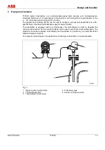
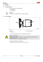
5.5
Electrical connections
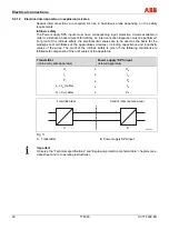
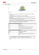
Resistance thermometers (RTD) / resistors (potentiometers)
A00244
3
1
2
5
6
4
4
6
5
4
4
6
2
2
2
2
3
3
3
3
3
3
3
3
4
1
1
1
1
1
1
1
1
2
1
2
3
4
5
6
7
8
+
-
JJ
J
J
J
J
J
J
B
A
C
1
1
...
30
(Ex)
42
VD
C
/
4
...
20
mA
Fig. 7
A DIP switch 1: on, hardware write
protection is enabled
DIP switch 2: no function
B Interface for LC display
C Ground terminal for sensor and
supply- / signal-cable shield
connection
1
Potentiometer, four-wire circuit
2
Potentiometer, three-wire circuit
3
Potentiometer, two-wire circuit
4
2 x RTD, three-wire circuit
1)
5
2 x RTD, two-wire circuit
1)
6
RTD, four-wire circuit
7
RTD, three-wire circuit
8
RTD, two-wire circuit
1) Sensor backup/redundancy, sensor drift monitoring, mean measurement or differential measurement
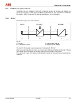
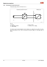
Thermocouple / voltage and resistance thermometer (RTD) / thermocouple combinations
A00245
+
-
+
-
+
-
+
-
+
-
+
-
+
-
7
6
5
5
5
5
4
6
6
6
2
2
3
3
3
1
1
1
J
J
J
3
1
2
5
4
6
+
-
D
C
4
3
2
5
6
+
-
5
6
2
2
2
+
-
1
2
1
1
1
1
A
B
E
1
1
...
30
(Ex)
42
VD
C
/
4
...
20
mA
Fig. 8
A Sensor
1
B Sensor
2
C DIP switch 1: on, hardware write
protection is enabled
DIP switch 2: no function
D Interface for LC display
E Ground terminal for sensor and
supply- / signal-cable shield
connection
1
2 x voltage measurement
1)
2
1 x voltage measurement
3
2 x thermocouple
1)
4
1 x thermocouple
5
1 x RTD, four-wire circuit, and thermocouple
1)
6
1 x RTD, three-wire circuit, and thermocouple
1)
7
1 x RTD, two-wire circuit, and thermocouple
1)
1) Sensor backup/redundancy, sensor drift monitoring, mean measurement or differential temperature measurement


