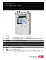
ABB TCC300 Quick Start Manual Download Page 6

6

*

 Power Flow Reverse setting screens are only available when the “Reverse Power Operation” selection under “Common Settings” 

is selected to either: REGULATE REVERSE,REG. R  MEASURED SRC, DISTRIBUTED GENERATION, AUTO DETERMINE orAUTO 
DETERMINE MEASURED. If Distributed Generation is selected, then only LDC values can be set.Selecting BLOCK, IGNORE or 
RETURN TO NEUTRAL disables the Power Flow Reverse setting screens.

Menu screens

Active Setpoint Profile or Setpoint Profile 

Selected for Editing

Limits    1

Profile Settings

Common Settings 1

Block Raise Voltage

xxx.x Volts

Block Lower Voltage

xxx.x Volts

Runup Deadband

x.x Volts

Current Block Limit

xxx mA

Runback Deadband

x.x Volts

Runup Enable/Disable

disable

Active Profile

Profile :1

Edit Profile 1 Name

"Empty"

Profile to Edit

Profile :1

Repeats for 

Profiles 2-4

LDC Selection

RX

Timer Reset

INTEGRATING

Timer Characteristic

DEFINITE

Power Direction Bias

NONE

Rev Power Operation

BLOCK *

Power Flow Fwd 1

Bandcenter Fwd

xxx.x Volts

LDC X  Fwd

x Volts

Bandwidth Fwd

x.x Volts

LDC Z  Fwd

x Volts

LDC R  Fwd

x Volts

With LDC R,X

With LDC Z

Definite(Inverse) Delay 

Fwd

xx  Sec

Bandcenter Rev

xxx.x Volts

Bandwidth Rev

x.x Volts

Power Flow Reverse 1

LDC X  Fwd

x Volts

LDC Z  Fwd

x Volts

LDC R  Fwd

x Volts

With LDC R,X

With LDC Z

Definite(Inverse) Delay 

Fwd

xx  Sec

VAr Bias    1

Disable on Rev Pwr

disable

VAr Bias Method

Step

Set VAr Bias Method

disable (Step, Linear)

Fwd Max Cap Bnk Size

12000 KVAr

Rev Max Cap Bnk Size

12000 KVAr

Lead % Pickup

75

Lag % Pickup

75

VAr Bias Volt Step

1.0 Volts

Max VAR Bias Time

300 mins

Curr Mult Base Value

0

Disable on Rev Pwr

disable

Set VAr Bias Method

Linear

Linear V Bias -X

0 Volts

Normlzd Lin V Bias -X

x.x Volts

Linear V Bias -X Lmt

0.0 Volts

Linear V Bias +X

0 Volts

Normlzd Lin V Bias +X

x.x Volts

Linear V Bias +X Lmt

0.0 Volts

To Profile

Settings

To

VAr Bias

Voltage Reduction 1

VRed Turnoff Timer

0 Min

Smart VR

disable

Save VR at Power Off

DON"T SAVE

Standard VR

ENABLE

Reduction Step 1 %

2.5

Reduction Step 3 %

7.5

Reduction Step 2 %

5.0

SETPOINTS

MNTR           CNFG

CONFIGURATION

SETP           COMM

COMMUNICATION

CNFG           UTIL

*

*

Summary of Contents for TCC300

Page 1: ...Voltage Reduction Steps Shortcuts arrows 4 SETP Access to the Setpoints screens 5 MNTR Access to the Monitoring screens 6 ENT UTL Push button Access to the Utilities screens and enter button 7 CNFG A...

Page 2: ...two periodic flashes indicates Level 2 Voltage Reduction Continuous illumination and three periodic flashes indicates Level 3 Voltage Reduction MANUAL LED Indicates automatic control is disabled and i...

Page 3: ...13 14 15 16 17 18 19 20 21 22 23 24 Fuse Amp Voltage Input Polarity Load Current Return See Note 2 Voltage Input Return See Note 2 Load Current Polarity 0 2 A Circulating Current Polarity 0 2A Circul...

Page 4: ...ng the current inputs Exercise care during installation operation and maintenance procedures The equipment described in this manual contains voltages high enough to cause serious injury or death Only...

Page 5: ...l xx Min Demand Load Voltage xxx x Volts Demand Pri Current xxx x Amps Demand Pri Watts x xx MW Demand Pri VArs x xx MVArs Demand Pri VA x xx MVA Demand Interval xx Min Min Load Voltage E x x Volts Ma...

Page 6: ...Power Flow Fwd 1 Bandcenter Fwd xxx x Volts LDC X Fwd x Volts Bandwidth Fwd x x Volts LDC Z Fwd x Volts LDC R Fwd x Volts With LDC R X With LDC Z Definite Inverse Delay Fwd xx Sec Bandcenter Rev xxx...

Page 7: ...er Display Option SINGLE_PHASE Fast Volt Recovery disable Fast Volt R Setting x x V Regulator Type TYPE A Output Selection CONTINUOUS Output Pulse X X Sec Low Current Block disable Tap Limits ENABLED...

Page 8: ...KT DVAR2 Sensitivity x x DVAR2 Reac I Lmt xxx mA DVAR2 I Ratio x xx Paralleling Type MASTER FOLLOWER MASTER FOLLOWER NONE Paralleling Address xx Num Devices x T P R Timeout xxxxx ms Breaker Option xxx...

Page 9: ...Validation disable Substation Address DNP x Feeder Address DNP x Comm Address DNP 1 Mdbus 1 Baud Rate 9600 Parity NONE Stop Bits ONE STOPBIT Sync Time 2 mS Output Pulse 1 5 Sec Comm Access Security d...

Page 10: ...S Coefficient 8192 X Circ Cal Coefficien 32767 X Circ Sin Coefficient 0 X Circ Cos Coefficient 8192 X LED Scroll Test Press ENT to begin Input Test Press ENT to Begin Output Test Press ENT to test But...

Page 11: ...11...

Page 12: ...ht 2016 ABB All rights reserved Contact us ABB Inc EPMV Distribution Automation 4300 Coral Ridge Drive Coral Springs FL 33065 USA Phone 1 800 523 2620 Phone 1 954 752 6700 Fax 1 954 345 5329 www abb c...

Reviews: