2
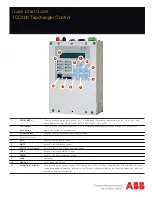
Leds
RAISE LED
Out of Band Low Voltage
LOWER LED
Out of Band High Voltage
REV PWR LED
Indicates reverse power flow
OK LED
Illuminates to indicate the micro controller is functioning properly and is extin-
guished when a Motor Seal-in Failure Block is in effect
COM1 TX/RX LEDS
Indicates when control is transmitting and/or receiving data
ALARM LED
Indicates any of the programmable alarms are activated
V/RED LED
Indicates voltage reduction has been invoked
- Continuous illumination and one periodic flash indicates Level 1 Voltage
Reduction
- Continuous illumination and two periodic flashes indicates Level 2 Voltage
Reduction
- Continuous illumination and three periodic flashes indicates Level 3 Voltage
Reduction
MANUAL LED
Indicates automatic control is disabled and in manual mode
LOCAL LED
Indicates control is switched into Local mode, cannot command control to raise or
lower via SCADA
T
X
Top View
Front
Fiber Optic V-Pin
Connector (optional)
Fiber Optic
ST Connector
RJ-45 Ethernet over
Copper (optional)
Control Power
Backup Input
BlueTooth
Ethernet over Fiber
Optic (optional)
RS-485
RS-232 DE9S
T
X
Bottom View
In-Line, 6-Pin Connector
for the M-2025B, C or D
Current Loop Module
24-Pin Blue Connector for
TCC300 Adapter Panels or
Direct Connection
Source Voltage Input
One Aux Output
Three Aux Inputs
Front
External connection locations
Summary of Contents for TCC300
Page 11: ...11...


