background image

I N S TA L L AT I O N ,  O P ER AT I O N  A N D  M A I N T EN A N C E  M A N UA L

16

Additional features include provision for padlock, when maintenance is required.

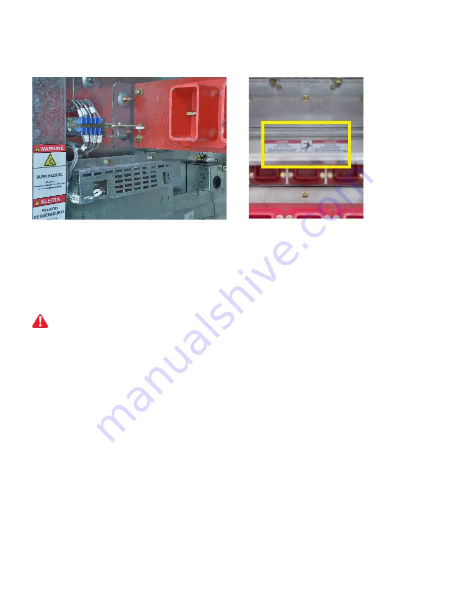
Truck operated contact
The TOC interacts with the position of the contactor, either “CONN.”, “DISCONN.” or intermediate positions. 

Note: TOC are factory calibrated, no further adjustment is necessary.

Line side shutter
The contactor compartment features a mechanical shutter lock to prevent access to the line side bus when the 
contactor is not in the compartment.

1.  Use a Lift Truck to move the contactor to the height of the compartment.
2.  Insert the tray guides of the Lift Truck in position in the compartment slots.
3.  Release the contactor of the tray with the front hand grips and slide them firmly to the compartment until reach 

the slots located on the rails of the compartment.

4.  Release Lift Truck.

At this point the Contactor is not connected to the load side bus. The position indicator is “DISCONN.” 
(extracted) and the status indicator is “OPEN”. 
The automatic secondary pins are connected to the contactor control board, which can close the contactor for 
testing in the status “CLOSED”.

Contactor mounting in compartment
The contactor is located outside the compartment ready to be inserted.

Fig. 14 TOC

Fig. 15 Line side shutter

Contactor compartment operation

 Do not attempt to deactivate the shutter system. It only operates when the contactor is in the compartment. 
Hazardous voltage can cause electrical shock and burns. Disconnect power, then earth and short-circuit 
before accessing for any components in this area.

DANGER

NOTICE

Before putting the contactor into the contactor compartment, place the automatic secondary at its initial
position (at the front of the compartment).

Summary of Contents for SafeGear MCC

Page 1: ... ELECTRIFICATION PRODUCTS SafeGear Motor Control Center Arc resistant metal clad construction Installation operation and maintenance manual ...

Page 2: ... Medium voltage SafeGear Motor Control Center controlling energy for a safe world ...

Page 3: ...003 Location site preparation 004 009 Indoor installation 010 012 Testing and final inspection 012 013 Putting into service 013 015 Standard construction 016 017 Contactor compartment operation 019 022 Maintenance 023 026 Plenum installation 027 032 Appendix A 033 040 Appendix B 041 044 Appendix C 045 046 Appendix D ...

Page 4: ...ions The instructions are general in nature They cover requirements for installation setup checkout and maintenance as applied to ABB medium voltage Motor Control Centers MCC These instructions do not attempt to cover all variations and combinations of equipment and installations Information on particular installations appears in the following Bills of materials that list electrical devices and eq...

Page 5: ... damage or loss Check the contents against the packing list before discarding any packing material Notify the carrier and ABB at once of any discrepancies If there is damage from improper handling file a claim for damages at once with the carrier and notify ABB Note ABB standard shipments are FOB Factory ABB is not responsible for damage after delivery of the equipment to the carrier unless otherw...

Page 6: ...ings supplied for the particular order Drawings show top and front views of the lineup primary and secondary connection diagrams and Bills of Materials Study these drawings and the following recommendations before preparing the site plan drawings Location Locate the lineup in accordance with local regulations Clearances at the front should allow installation and removal of the draw out equipment a...

Page 7: ...l doors and panels To move the shipping sections to their final position one of four methods can be used Forklift place forks through locations provided in the shipping bases see Figures 01 and 02 Lift the MCC frames slowly and tilt forks slightly rearward to balance Move carefully into the final position taking into account the center of gravity see Figure 04 Drilling or punching of holes in the ...

Page 8: ... the shipping bases attached Removal of the Shipping Base Once the units are in their final place the shipping bases can be removed Open the equipment doors Remove the bolts holding each of the three shipping bases to the equipment If circuit breakers were installed for shipment the lower position breakers will need to be removed prior to this step Close and secure all doors and panels Raise the u...

Page 9: ... follow these circuits and remove temporary connections from current transformer secondaries see Figure 1 Temporary jumpers protect against voltages that may occur if the current transformer primaries carry currents while the secondary circuits are still not complete With the secondary circuits connected remove the jumpers Power cable penetrations top entry or bottom entry into the equipment shoul...

Page 10: ...e all packing material and lift plenum sections to the top of the MCC by suitable lifting means Each section is then bolted to the plenum base mounted on the MCC roof and also to the adjoining plenum section with provided hardware Once the roof mounted plenums are in place install additional plenum sections for venting outside the building one at a time starting at the MCC boundary see Fig 2 As ea...

Page 11: ...nt Drawings The contact surfaces of the bus at bolted joints are plated Clean contact surfaces with a clean cloth and an OSHA approved solvent Note Take care not to remove or tarnish plating Remove barriers to access the main bus compartment Bolt the main bus together using supplied hardware Conductivity of a bolted joint depends on the pressure or torque applied Note All bolted joints must be tor...

Page 12: ...rea for connection of primary cables is provided in the cable compartment either through the roof or floor as indicated in the General Arrangement drawings The gland plates are made of 074 stainless steel these plates must be utilized in the final assembly Holes for entrance of power cables or conduits must be cut in the gland plate s and a sealing type bushing used Connection to control source Th...

Page 13: ...a separate temporary control power source of the required control voltage rating The temporary source must have a properly coordinated backup protective device in the circuit Set the device to clear any faults that might occur Initially all contactors should be racked out DISCONN position and the main circuit deenergized and grounded When AC control power is from control power transformers in the ...

Page 14: ...DISCONN position 8 De energize the control circuit If AC control power is from transformers in the MCC remove the separated temporary control power source Reinstall all fuses in the transformer circuit 9 Set all relays regulators and other devices for proper operation of loads The factory does not set the relays 10 Remove shorting screws from the terminal blocks in the current transformers circuit...

Page 15: ...m supplied with the equipment Finalinspection Typical circuit diagram HCV 5HA Safety precautions Fig 6 Standard operation circuit diagram of normally energized type Putting into service The contactor or cutout device of the local control power circuit must be opened when is used a separated control power source There are hazards of electrical shocks and or burns whenever working in or around elect...

Page 16: ...trol power source 5 Energizethemainbusclosingthemaincircuitbreaker verifythattherelaysandotherinstrumentsarefunctioning correctly 6 Place the contactors from the out position DISCONN to the inserted position CONN 7 Close the desired contactors Standard construction Contactor compartment The principle of manufacturing is modular for 400 and 720 A contactors the compartment dimensions are 30 wide 33...

Page 17: ...tor Primary connection Consists of a set of three copper contact fingers compressed by springs these can be inspected by removing the contactor from the compartment Line side finger contacts apply the correct pressure over the terminals achieving self alignment of the devices All copper parts are silverplated tin plated are an option for better conduction Bus bars and supports Bus bars are electro...

Page 18: ...rent 400 A 720 A Interrupting capacity 7000A RMS Symmetrical 5000V Max 7200 A 4500A RMS Symmetrical 7200V Max Peak withstand current 15 8 kA 20 kA Impulse withstand 60 kV Permissible switching 1200 Hour 300 Hour 600 Hour 300 Hour Mechanical life operations 2 500 000 250 000 1 000 000 200 000 Electrical life operations 250 000 250 000 200 000 Closing time 50 110 ms 80 120 ms Standard opening time 1...

Page 19: ... reach the slots located on the rails of the compartment 4 Release Lift Truck At this point the Contactor is not connected to the load side bus The position indicator is DISCONN extracted and the status indicator is OPEN The automatic secondary pins are connected to the contactor control board which can close the contactor for testing in the status CLOSED Contactor mounting in compartment The cont...

Page 20: ...causing damage in the connectors that finally can produce loss of the control signals Please review following instructions previous to insert the controller into the MCC cell 2 Review that frontal tongue is not damaged or folded during any commissioning or maintenance activities also review good conditionofthespringbellowof the tongue 3 The tongue of the secondary connectionsmechanismshallbe align...

Page 21: ...in that is locking the door 3 Move up the tool to release the locking pin that is locking the door 1 Close the door bolting all the screws 2 Ensure that the contactor is open OPEN 3 Turn the door shutter to insert the lever 4 Insertthehandleandturnclockwise10completecycles Continuesuntilthemechanicalstoppositionisactivated The contactor is now in the inserted position CONN connected to the main bu...

Page 22: ... or lift truck This ramp carries the contactor outside the contactor compartment for maintenance or servicing Door hole 10 32 UNF screw Flat screwdriver Door hole Limit the using of solvents to remove grease and contaminants to the primary conductors insulators and metal surfaces without paint Do not use alcohol or freon Use OSHA approved solvents according to local regulations Use a nonflammable ...

Page 23: ...air for inaccessible areas Remove the covers of all panel devices where possible Check wiring for secure connections Clean contacts on relays and switches wherever necessary Replace covers Remove air filters when used Flush with clean water if necessary Follow the recommendations of any individual device instructions furnished for maintenance of the device Perform maintenance of contactors as reco...

Page 24: ...ity of the company is to facilitate subsequent recycling or disposal at the end of the product s life During disposal of the product it is always necessary to act in accordance with all local and national legal requirements that are in effect at the time of disposal Methods of disposal Disposal can either be carried out in a manner of ways depending upon material of product Below is the recommende...

Page 25: ...ility or warranties arising from course of dealing or usage of trade are made regarding the information recommendations descriptions and safety notations contained herein In no event will ABB be responsible to the user in contract in tort including negligence strict liability or otherwise for any special indirect incidental or consequential damage or loss whatsoever including but not limited to da...

Page 26: ...l building code requirements 4 The exhaust vent section shown in Figure 3 should be installed in the building wall and connected to the last plenum section as shown in Figure 4 The opening of the exhaust vent section cannot be installed pointing upwards due to environmental considerations 5 Theareaoutsidetheplenumexhaustventneedstobekeptclearofpersonnelandequipmentduetothepotential for pressurized...

Page 27: ...ses escape into the building Do not remove exhaust mesh incandescent particles might escape the MCC in case of an arc fault Recommended plenum exhaust keep clear area Clear area 3 SAE grade 5 screws 30 40 lb ft torque to bolt MCC Plenum 1 3 8 16 UNC X 1 0 in Opening must be sealed weather tight by others Building wall Vent exhaust Optional aditional plenum sections Diameter 96in 2 44m 2 3 8 16 UNC...

Page 28: ...25 SAFEGEAR MOTOR CONTROL CENTER ARC RESISTANT METAL CL AD CONSTRUCTION in mm General dimensions ...

Page 29: ...ABB MIGHT BE DONE OR OF THE POSSIBLE HAZARDOUS CONSEQUENCES OF EACH CONCEIVABLE WAY NOR COULD ABB INVESTIGATE ALL SUCH WAYS ANYONE USING SERVICE PROCEDURES OR TOOLS WHETHER OR NOT RECOMMENDED BY ABB MUST SATISFY HIMSELF THOROUGHLY THAT NEITHER PERSONAL SAFETY NOR EQUIPMENT SAFETY WILL BE JEOPARDIZED BY THE SERVICE METHOD OR TOOLS SELECTED INFORMATION CONTAINED IN THIS MANUAL IS BASED ON THE LATEST...

Page 30: ...on guide Models shown in this document may not match exactly with the product you received 3 Safety practice Safety glasses gloves and steel toe shoes shouldbeusedasstandardsafetypractice 4 Target result 5 Tools required not supplied 6 Parts required Colors of parts in this document do not represent actual colors it is for illustration purposes only 8 or longer Extension 1 9 16 Socket 1 Ratchet 1 ...

Page 31: ...nt The line up you received might include more than one frame on either side the rest of the frames are assembled together in the plant and excluded from the pictures in this manual for simplicity 02 Open the LV compartment door and the controller door in the left frame Look inside the left frame on the right and notice the Tinnerman nuts installed highlighted in green 01 02 Tinnerman Nuts Bolts T...

Page 32: ...ame wall that is highlighted in green Except in the part where says Bolts That means that the bolts will be screwed from the right frame to the left frame 04 This diagram is for illustration purposes only it may not fully represent all or any of the frames you received 05 The picture shows a side view of the frame indicating the holes for each bolt 06 The next picture shows the location of the Tin...

Page 33: ... frame Insert a bolt in every hole in the right frame at the left side that is aligned with a Tinnerman nut on the left side Notice the Tinnerman nuts behind the highlighted panel NOTE For main bus installation consult 10 Main Bus Assembly Manual 08 The following picture shows the location of the Tinnerman nuts and where the bolts will be installed 07 Rear view of the frames ...

Page 34: ...R CONTROL CENTER ARC RESISTANT METAL CL AD CONSTRUCTION 09 Place a bolt in all holes 22 shown highlighted in blue Before to place the main bus bars place a bolt for each hole through bus support highlighted in green 09 ...

Page 35: ...general instruction guide Models shown in this document may not match exactly the product you received 3 Safety practice Safety glasses gloves and steel toe shoes should be used as standard safety practice 4 Tools required not supplied Wrench Socket Socket head Screwdriver 7 16 Torque wrench 9 16 Socket Ratchet x 13 Bolt Length de pends on bus rating 13 Hex nut Flat washer Lock washer Seal putty C...

Page 36: ...rtment doors in the back of the two frames where the main bus is to be installed and remove the upper and lower bus barriers in both frames 02 Start by removing the bus side cover in both frames the number one first and then the number two 03 Remove the top bus cover in both frames the number three first and then the number four 01 02 ...

Page 37: ...INSTALL ATION OPER ATION AND MAINTENANCE MANUAL 34 6 Procedure 4 3 2 1 03 4 3 ...

Page 38: ...T METAL CL AD CONSTRUCTION 04 Remove the plastic bolts of the bus boots in some cases these bolts are not in the bus boots but in a bag they are included Remove all the bus boots The bus boots must be reinstalled after the main bus is installed 04 ...

Page 39: ...TENANCE MANUAL 36 05 Slide the main bus bars through the through three openings in the bus support red rectangular sheet installed bet ween both frames 06 The picture shows the bus with the boots removed 05 Slide bus bars through here ...

Page 40: ...e the main bus bar Once the main bus bar is placed tighten the eight bolts If spacers are needed they are going to be supplied by the factory 08 This picture is for reference only it may not represent your actual setup Please refer to the standard or special drawing provided to you by the project engineer for guidelines Use the torque wrench to tighten all 13 UNC bolts they must be tightened to AB...

Page 41: ...TENANCE MANUAL 38 09 Reinstall all the bus boots 10 Place the plastic bolts and tighten them 11 Apply the provided seal putty around the inside rim of the through bus support in the right frame Cut any excess putty 10 11 12 Seal Puttty ...

Page 42: ...bus barriers start by reinstalling the top bus cover the number four first followed by the number three followed by the side bus covers the number one followed by number two 14 Connect the ground bus bar from frame to frame It is located in the back frame highlighted in green 4 3 2 1 13 14 ...

Page 43: ...s document may not match exactly the product you received 3 Safety practice Safety glasses gloves and steel toe shoes should be used as standard safety practice 4 Tools required not supplied Philips screwdriver 1 5 Distribution of the electrical connections The picture shows the distribution of the electrical connections such as customer connection control relays and power supply of the control ci...

Page 44: ...ou by the project engineer to find the shipping splits and exact frames where rewiring is necessary Locate the wires to be interconnected Refer to the interconnect diagram to find the frame housing the wires to be interconnected 02 Transfer all the wires to be interconnected from one frame to the next frame through the opening provided in the LV compartment 02 ...

Page 45: ...INSTALL ATION OPER ATION AND MAINTENANCE MANUAL 42 03 Route the wires according to the interconnect diagram 04 Remove the plastic cover for to place the wires 03 04 A ...

Page 46: ...he wires are shipped tagged and lugged from the factory and are ready to be connected Place the wires across the shipping splits or wiring Interconnects like in the green square that s shown 06 Place the plastic cover and connect the wires according to the connection diagram 05 06 ...

Page 47: ...Hardware Size inch Torque value 5 16 18 hex head 20 lb ft Max Target 17 lb ft 13 lb ft Min 3 8 16 carriage bolt 40 lb ft Max Target 35 lb ft 30 lb ft Min 3 8 16 hex bolt 40 lb ft Max Target 35 lb ft 30 lb ft Min 3 8 16 steel threaded stud CT mounting 20 lb ft Max Target 19 ft lb 18 ft lb Min 3 8 16 fiberglass threaded stud CT mounting 12 lb ft Max Target 11 ft lb 10 ft lb Min 1 2 13 hex bolt 75 lb...

Page 48: ...leteness accuracy reliability suitability or availability with respect to the information products services or related graphics contained in the document for any purpose Any reliance placed on such information is therefore strictly at your own risk ABB reserves the right to discontinue any product or service at any time 1YEPMSC2520E001 Copyright 2020 ABB All rights reserved Your sales contact www ...

Reviews: