background image

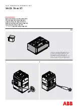
SACE Tmax XT | ABB

3

4

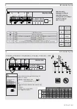
DIP LSI/LSIG Trip Unit

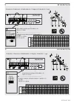
DIP LSI/LSIG Trip Unit

Default setting
Settaggio di default
Default-Einstellung


Configuration par défauit


Ajuste de default

默认手动设置

L

S

I

InN

0,4In; 3s

Off; 0,1s

5,5In

Off; 0,1s

3p = Off
4p = 50%

G

 Green

 L

 Red

LED Fixed = L pre alarm (0,9 * I1 < I < 1,2 * I1)

LED Blinking =  L alarm (I > 1,2 * I1)

 S

 Red

G

 Red

L | S | I | G

 Red

LED Fixed = Device active

LED Blinking  = G alarm (I > I4)

All LED Blinking = Parameters inconsistency - L = S or S 

_

>

I

.

All LED Blinking without Parameters inconsistency = generic fault (please contact ABB)

 LED

 Color

CONDITION  Run time

LED Blinking  = S alarm (I > I2)

Notes-Note-Anmerkungen-Nota-Notas-

注释

Ifault > I1 = Alarm

Alarm

 = Red-Rosso-Rot

Vermelho-Rojo - 

红色

(

)

Example-Esempio-Beispiel-Exemple-Ejemplo-

In=630A
I1=630 x (0,4 + 0,4) = 504A
t1= 12s@1512A (3xI1)

Protection L- Protezione L- Schutzfunktion L - Proteção L- Protección L - L

例子

In (A)

0,4

0,42

0,44

0,96

0,98

1

IEC - UL 250

100

105,0

110,0

240,0

245,0

250

UL

300

120

126,0

132

288

294,0

300

IEC

320

128,0

134,4

140,8

307,2

313,6

320

IEC - UL 400

160,0

168,0

176,0

384,0 392,0

400

UL

600

240

252

264

576

588

600

IEC

630

252

264,6

277

605

617,4

630

XT5

I1 (In)

Summary of Contents for SACE Tmax XT

Page 1: ...ns 1SDH002011A1518 Montageanleitung 1SDH002011A1518 Instructions de montage 1SDH002011A1518 Instrucciones de montaje 1SDH002011A1518 1 1 2 Sganciatori Ekip LSI Ekip LSIG XT5 Trip Unit Ekip LSI Ekip LSIG XT5 Auslöser Ekip LSI Ekip LSIG XT5 Dèclencheur Ekip LSI Ekip LSIG XT5 Relé Ekip LSI Ekip LSIG XT5 电子脱扣器 Ekip LSI Ekip LSIG XT5 ...

Page 2: ...inking without Parameters inconsistency generic fault please contact ABB LED Color CONDITION Run time LED Blinking S alarm I I2 Notes Note Anmerkungen Nota Notas 注释 Ifault I1 Alarm Alarm Red Rosso Rot Vermelho Rojo 红色 Example Esempio Beispiel Exemple Ejemplo In 630A I1 630 x 0 4 0 4 504A t1 12s 1512A 3xI1 Protection L Protezione L Schutzfunktion L Proteção L Protección L L 例子 In A 0 4 0 42 0 44 0 ...

Page 3: ...0 IEC 320 320 480 640 800 960 1120 1440 1760 2080 2240 2400 2560 2720 2880 3200 IEC UL 400 400 600 800 1000 1200 1400 1800 2200 2600 2800 3000 3200 3400 3600 4000 UL 600 600 900 1200 1500 1800 2100 2700 3300 3900 4200 4500 4800 5100 5400 6000 IEC 630 630 945 1260 1575 1890 2205 2835 3465 4095 4410 4725 5040 5355 5670 6300 I2 In XT5 In A 1 1 5 2 2 5 3 3 5 4 5 5 5 6 5 7 7 5 8 8 5 9 10 IEC UL 250 250...

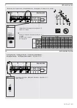
Page 4: ...N 100 In Setting Neutral Settaggio Neutro Einstellung Neutralleiter Réglages Neutre Configuraciones Neutro 设定频率和中性 Protection G Protezione G Schutzfunktion G Proteção G Protección G G In A 0 2 0 25 0 45 0 55 0 75 0 8 1 IEC UL 250 50 62 5 113 138 188 200 250 UL 300 60 75 135 165 225 240 300 IEC 320 64 80 144 176 240 256 320 IEC UL 400 80 100 180 220 300 320 400 UL 600 120 150 270 330 450 480 600 IEC...

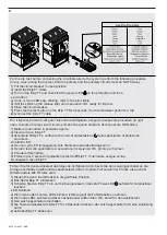
Page 5: ...ganciatore di protezione sia acceso Controllo LED a Se uno o più LED lampeggiano fare riferimento alla tabella degli errori b Se tutti i led sullo sganciatore si accendono in sequenza OK pronto per trip test 4 Chiudere l interruttore 5 Premere per 2 secondi il pulsante trip test dell Ekip TT l interruttore esegue un trip Scollegare il cavo Ekip TT 1 Stellen Sie den Cricuit Breaker in die geöffnete ...

Page 6: ...cteur en position ouverte 2 Brancher le câble Ekip TT 3 Allumez l Ekip TT et vérifier que la Led d alimentation sur le déclencheur de protection est allumée Contrôle des LED a Si une ou plusieurs LED clignotent se reporter au tableau des erreurs b Si toutes les Led sur le déclencheur s allument en séquence OK prêt pour le test de déclenchement 4 Fermer le disjoncteur 5 Appuyer sur le bouton de test...

Reviews: