ABB | SACE Emax 2
Ekip Dip
2 - Operator interface
33 | © 2023 ABB | 1SDH001000R0002 - ECN000297030
LED
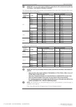
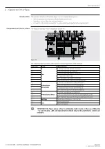
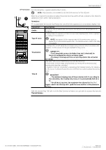
The LEDs are useful on Ekip Dip in order to distinguish and identify various types of information on the
protection trip unit, the circuit-breaker and state of the line currents.
The LEDs combined with the protections provide various information, through different combinations of
lighting and blinking.
NOTE:
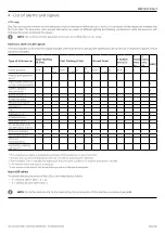
all the combinations related to protection LED signals are described in chapter
Self-
diagnosis and signalling
, on page
Protections: Thresholds and
timing
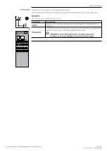
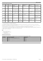
The thresholds of all the protections can be modified with various dip-switches, as specified on the
serigraph of the interface.
The values of the protections make reference to the current In, a nominal value defined by the Rating Plug.
The times and the curves of the protections can be modified with various dip-switches, as specified on
the serigraph of the interface.
IMPORTANT:
•
Changes to the thresholds and times must be made in the absence of protection alarms.
•
Modifications carried out in alarm conditions are accepted by the trip unit when resting
condition is restored (absence of protection alarms).
Settings
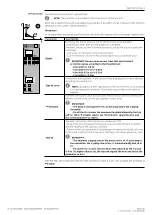
Two further settings are available:
•
Neutral
allows activation and adjustment of the protections on the neutral pole.
•
Frequency
allows the selection of the installation frequency.
iTest pushbutton
The iTest pushbutton is useful for three operations:
• Perform tests (circuit-breaker opening test and LED test).
• Reset the signal of the tripped protection. This operation can be performed when the circuit-breaker
is both open and closed and with currents present, by pressing the push-button for about 1 second
(the signal disappears when the push-button is released).
• With the trip unit off, check the information relating to the switch-off or tripping event.
NOTE:
with the trip unit off, pressing of the iTest button switches on (for approximately 4
seconds):
• the power-on LED, if the trip unit is off due to an energy drop (primary current less than the
minimum level of operation, removal of auxiliary power supply with circuit-breaker open,
etc…).
• the protection tripped LED if the trip unit is off due to a protection trip.
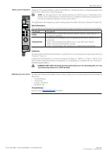
Test connector
The test connector allows the connection of Ekip TT and Ekip T&P modules (purchased separately), in
order to perform the following operations:
• The release can be provided with temporary power supply for state verification and conduction of
trip tests and LED tests (option available with all front interface modules).
• Analysis, supervision and setting of additional parameters through external communication test
units (Ekip T&P).

