


14
RS85
VIBR ATING FORK LEVEL SWITCH | OI/RS85-EN REV. K
Fault mode
If a fault is detected, either electrical or mechanical, LED 2 will
blink in RED and the normal ON relay is de–energized. This
LED is integral to the modular electronics and can only be
seen through the glass viewing cover.
Table 5 – Fault mode
Fault
Reason
Remedy
Does not
switch
No Power
Check power
Faulty wiring
Check wiring
Faulty electronic Module
Replace module
Density of liquid too low
Confirm that density is above
.5 SG
Fork encrusted with too
much buildup
Clean fork
Fork corroded or bent
Exchange fork and
process connection (requires
sending to factory)
Contacts welded together
(after short–circuit)
Replace module; put fuse in
contact circuit
Switches
incorrectly
Fail–safe mode
set wrong
Set correct mode at electronic
module
Sporadic
faulty
switching
Relay switches on & off
while in dry fork conditions
Recalibrate switch in process
connection
Thick heavy foam, very
turbulent conditions,
foaming liquid
Set time delay
Extreme RFI
Use shielded cable
Water in housing
Remove water, screw cover and
cable gland tight
Output overloaded
Reduce load: (cable) capacitance
5 Troubleshooting
.
.
2
.
.
.
.
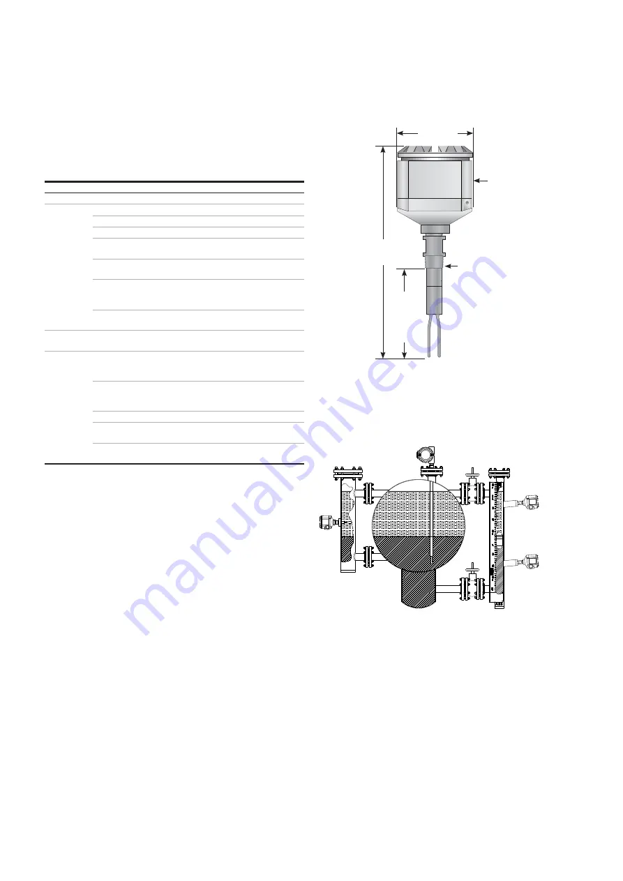
RS85
switches
mounted
in external
chamber
RS85 dual
compartment
housing and custom
insertion length
RS85
switches
mounted in
KM26 magnetic
level gauge
Standard
86 mm
(3⅜ in)
PL*
279 mm (11 in)
standard
111 mm
(4⅜ in)
19 mm (¾ in)
MNPT
standard
19.05 mm (¾ in)
FNPT conduit
Standard single compartment dimensions
Resonator sample applications
Figure 28
Figure 29