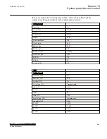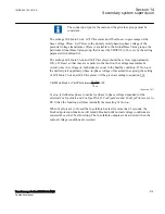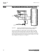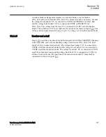
The reference voltage can be phase-neutral A, B, C or phase-phase A-B, B-C, C-A or
positive sequence (Require a three phase voltage, that is VA, VB and VC) . By setting
the phases used for SESRSYN, with the settings
SelPhaseBus1
,
SelPhaseBus2
,
SelPhaseLine2
and
SelPhaseLine2
, a compensation is made automatically for the
voltage amplitude difference and the phase angle difference caused if different setting
values are selected for the two sides of the breaker. If needed an additional phase angle
adjustment can be done for selected line voltage with the
PhaseShift
setting.
15.1.2.2
Synchronism check
M12309-6 v10
The main purpose of the synchronism check function is to provide control over the
closing of circuit breakers in power networks in order to prevent closing if conditions
for synchronism are not detected. It is also used to prevent the re-connection of two
systems, which are divided after islanding and after a three pole reclosing.
Single pole auto-reclosing does not require any synchronism check
since the system is tied together by two phases.
SESRSYN (25) function block includes both the synchronism check function and the
energizing function to allow closing when one side of the breaker is dead. SESRSYN
(25) function also includes a built in voltage selection scheme which allows adoption
to various busbar arrangements.
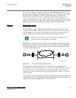
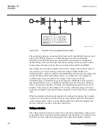
en04000179_ansi.vsd
~
~
~~
~~
ANSI04000179 V1 EN-US
Figure 304:
Two interconnected power systems
Figure
shows two interconnected power systems. The cloud means that the
interconnection can be further away, that is, a weak connection through other stations.
The need for a check of synchronization increases if the meshed system decreases
since the risk of the two networks being out of synchronization at manual or automatic
closing is greater.
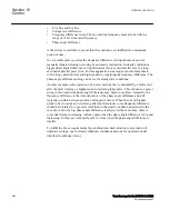
The synchronism check function measures the conditions across the circuit breaker and
compares them to set limits. Output is generated only when all measured conditions are
within their set limits simultaneously. The check consists of:
1MRK 504 163-UUS A
Section 15
Control
Transformer protection RET670 2.2 ANSI
679
Application manual
Summary of Contents for RELION RET670
Page 1: ...RELION 670 SERIES Transformer protection RET670 Version 2 2 ANSI Application manual ...
Page 2: ......
Page 48: ...42 ...
Page 64: ...58 ...
Page 74: ...68 ...
Page 104: ...98 ...
Page 194: ...188 ...
Page 518: ...512 ...
Page 618: ...612 ...
Page 648: ...642 ...
Page 666: ...660 ...
Page 672: ...666 ...
Page 682: ...676 ...
Page 844: ...838 ...
Page 868: ...862 ...
Page 956: ...950 ...
Page 964: ...958 ...
Page 1004: ...998 ...
Page 1014: ...1008 ...
Page 1015: ...1009 ...

