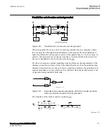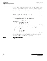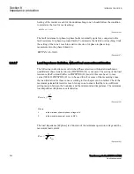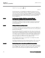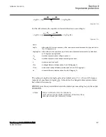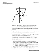
( )
( )
( )
( )
2
2
0
Im
Im
0
Re
Im
X m
B
K
B
B
×
=
+
EQUATION1428 V2 EN-US
(Equation 141)
Parallel line is out of service and grounded in both ends
SEMOD55087-77 v3
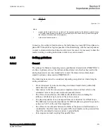
Apply the same measures as in the case with a single set of setting parameters. This
means that an underreaching zone must not overreach the end of a protected circuit for
the single phase-to-ground faults.
Set the values of the corresponding zone (zero-sequence resistance and reactance)
equal to:
R
0E
R
0
1
X
m0
2
R
0
2
X
0
2
+
--------------------------
+
è
ø
ç
÷
æ
ö
×
=
EQUATION561 V1 EN-US
(Equation 142)
X
0E
X
0
1
X
m0
2
R
0
2
X
0
2
+
--------------------------
–
è
ø
ç
÷
æ
ö
×
=
EQUATION562 V1 EN-US
(Equation 143)
8.3.3.6
Setting of reach in resistive direction
SEMOD55087-84 v7
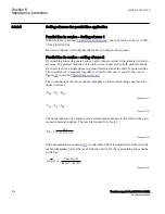
Set the resistive reach
R1
independently for each zone.
Set separately the expected fault resistance for phase-to-phase faults
RFPP
and for the
phase-to-ground faults
RFPE
for each zone. For each distance zone, set all remaining
reach setting parameters independently of each other.
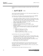
The final reach in resistive direction for phase-to-ground fault loop measurement
automatically follows the values of the line-positive and zero-sequence resistance, and
at the end of the protected zone is equal to equation
.
1
R
2 R1Zx
R0Zx
RFPEZx
3
IECEQUATION2303 V2 EN-US
(Equation 144)
2 X1Zx
X0Zx
arctan
2 R1Zx
R0Zx
loop
EQUATION2304 V2 EN-US
(Equation 145)
1MRK 504 163-UUS A
Section 8
Impedance protection
Transformer protection RET670 2.2 ANSI
279
Application manual
Summary of Contents for RELION RET670
Page 1: ...RELION 670 SERIES Transformer protection RET670 Version 2 2 ANSI Application manual ...
Page 2: ......
Page 48: ...42 ...
Page 64: ...58 ...
Page 74: ...68 ...
Page 104: ...98 ...
Page 194: ...188 ...
Page 518: ...512 ...
Page 618: ...612 ...
Page 648: ...642 ...
Page 666: ...660 ...
Page 672: ...666 ...
Page 682: ...676 ...
Page 844: ...838 ...
Page 868: ...862 ...
Page 956: ...950 ...
Page 964: ...958 ...
Page 1004: ...998 ...
Page 1014: ...1008 ...
Page 1015: ...1009 ...

