Table 18:
CT input channels used for the HV side CTs
Setting parameter
Selected value for both solutions
CTprim
400
CTsec
5
CT_WyePoint
ToObject
5. Enter the following settings for all three CT input channels used for the LV side CTs,
see table
"CT input channels used for the LV side CTs"
CT input channels used for the LV side CTs
Setting parameter
Selected value for Solution 1 (wye
connected CT)
Selected value for Solution 2 (delta
connected CT)
CTprim
1500
1500
866
3
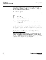
=
EQUATION1889 V1 EN-US
(Equation 15)
CTsec
5
5
CT_WyePoint
ToObject
ToObject
To compensate for delta connected CTs, see equation
.
6. Enter the following values for the general settings of the differential protection
function, see table
.
Table 19:
General settings of the differential protection
Setting parameter
selected value for both Solution 1
(wye conected CT)
Selected value for both Solution 2
(delta connected CT)
RatedVoltageW1
115 kV
115 kV
Rated VoltageW2
24.9 kV
24.9 kV
RatedCurrentW1
301 A
301 A
RatedCurrentW2
1391 A
1391 A
ConnectTypeW1
Delta (D)
WYE (Y)
1)
ConnectTypeW2
wye=y
wye=y
ClockNumberW2
1 [30 deg lag]
0 [0 deg]
1)
ZSCurrSubtrW1
Off
Off
ZSCurrSubtrW2
On
On
2)
TconfigForW1
No
No
TconfigForW2
No
No
Table continues on next page
Section 7
1MRK 504 163-UUS A
Differential protection
152
Transformer protection RET670 2.2 ANSI
Application manual
Summary of Contents for RELION RET670
Page 1: ...RELION 670 SERIES Transformer protection RET670 Version 2 2 ANSI Application manual ...
Page 2: ......
Page 48: ...42 ...
Page 64: ...58 ...
Page 74: ...68 ...
Page 104: ...98 ...
Page 194: ...188 ...
Page 518: ...512 ...
Page 618: ...612 ...
Page 648: ...642 ...
Page 666: ...660 ...
Page 672: ...666 ...
Page 682: ...676 ...
Page 844: ...838 ...
Page 868: ...862 ...
Page 956: ...950 ...
Page 964: ...958 ...
Page 1004: ...998 ...
Page 1014: ...1008 ...
Page 1015: ...1009 ...


