Substation A
Substation B
Z
lineAB,1
(pos. seq)
Z
lineAB,0
(zero seq)
Z
lineBC,1
(pos. seq)
Z
lineBC,0
(zero seq)
U
0A
U
0B
3I
0
Phase to earth fault
R
N
Z
T,1
(pos. seq)
Z
T,0
(zero seq)
Source impedance
Z
sc
(pos. seq)
en06000654.vsd
IEC06000654 V1 EN-US
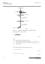
Figure 61:
Equivalent of power system for calculation of setting
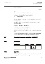
The residual fault current can be written:
phase
0
1
0
f
3U
3I
2 Z
Z
3 R
=
×
+
+ ×
EQUATION1948 V1 EN-US
(Equation 45)
Where
U
phase
is the phase voltage in the fault point before the fault
Z
1
is the total positive sequence impedance to the fault point. Z
1
= Z
sc
+Z
T,1
+Z
lineAB,1
+Z
lineBC,1
Z
0
is the total zero sequence impedance to the fault point. Z
0
= Z
T,0
+3R
N
+Z
lineAB,0
+Z
lineBC,0
R
f
is the fault resistance.
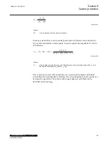
The residual voltages in stations A and B can be written:
(
)
0 A
0
T ,0
N
U
3I
Z
3R
=
×
+
EQUATION1949 V1 EN-US
(Equation 46)
OB
0
T ,0
N
lineAB,0
U
3I (Z
3R
Z
)
=
×
+
+
EQUATION1950 V1 EN-US
(Equation 47)
Section 8
1MRK 511 407-UEN C
Current protection
152
Phasor measurement unit RES670 2.2 IEC
Application manual
Summary of Contents for Relion RES670
Page 1: ...RELION 670 SERIES Phasor measurement unit RES670 Version 2 2 IEC Application manual...
Page 2: ......
Page 46: ...40...
Page 52: ...46...
Page 92: ...86...
Page 112: ...106...
Page 178: ...172...
Page 216: ...210...
Page 232: ...226...
Page 286: ...280...
Page 328: ...322...
Page 340: ...334...
Page 380: ...374...
Page 381: ...375...

