frequencies must also be within a range of +/- 5 Hz from the rated frequency.
When the synchronizing option is included also for autoreclose there is no reason
to have different frequency setting for the manual and automatic reclosing and the
frequency difference values for synchronism check should be kept low.
•
The frequency rate of change is less than set value for both U-Bus and U-Line.
•
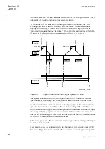
The closing angle is decided by the calculation of slip frequency and required pre-
closing time.
The synchronizing function compensates for measured slip frequency as well as the
circuit breaker closing delay. The phase angle advance is calculated continuously.
Closing angle is the change in angle during the set breaker closing operate time
tBreaker
.
The reference voltage can be phase-neutral L1, L2, L3 or phase-phase L1-L2, L2-L3,
L3-L1 or positive sequence. The bus voltage must then be connected to the same phase
or phases as are chosen for the line. If different phases voltages are used for the
reference voltage, the phase shift has to be compensated with the parameter
PhaseShift
, and the voltage amplitude has to be compensated by the factor
URatio
.
Positive sequence selection setting requires that both reference voltages are three
phase voltages.
10.1.2.2
Synchrocheck
The main purpose of the synchrocheck function is to provide control over the closing
of circuit breakers in power networks in order to prevent closing if conditions for
synchronism are not detected. It is also used to prevent the re-connection of two
systems, which are divided after islanding and after a three pole reclosing.
Single pole auto-reclosing does not require any synchrocheck since
the system is tied together by two phases.
SESRSYN function block includes both the synchronism check function and the
energizing function to allow closing when one side of the breaker is dead. SESRSYN
function also includes a built in voltage selection scheme which allows adoption to
various busbar arrangements.
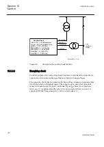
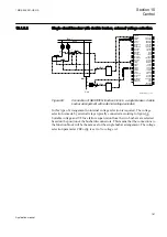
~
~
~~
~~
en04000179.vsd
IEC04000179 V1 EN
Figure 79:
Two interconnected power systems
shows two interconnected power systems. The cloud means that the
interconnection can be further away, that is, a weak connection through other stations.
Section 10
1MRK 505 291-UEN A
Control
184
Application manual
Summary of Contents for Relion REQ650
Page 1: ...Relion 650 series Breaker protection REQ650 Application manual ...
Page 2: ......
Page 20: ...14 ...
Page 26: ...20 ...
Page 48: ...42 ...
Page 82: ...76 ...
Page 90: ...84 ...
Page 160: ...154 ...
Page 178: ...172 ...
Page 264: ...258 ...
Page 288: ...282 ...
Page 302: ...296 ...
Page 330: ...324 ...
Page 338: ...332 ...
Page 339: ...333 ...

