Feeder Terminal
REF 542plus
1MRS756269
12
Technical data
Measurements
The REF 542plus uses the same analog inputs
both for measurements and protections.
Protection functions
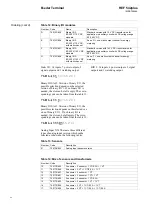
Table 1: Measurements
Quantity
Class
Range
Phase current, earth current
0.5
0.1 - 4 x I
n
Line voltage, phase voltage
0.5
0.2 - 1.5 x U
n
Active, reactive energy
2
-
Active, reactive, apparent power
1
-
Cos
ϕ
1
0 - 1
Frequency
0.02
-
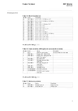
Table 2: Protection functions and operation time
Quantity
Range
Protection functions
Class 3
Operation time
Class 3 or minimum ±15 ms
Table 3: Current and voltage transformer input values
Quantity
Range
Rated current I
n
0.2 A, 1.0 A, 5.0 A
Rated voltage U
n
100 - 125 V AC
Rated frequency f
n
50 Hz/60 Hz
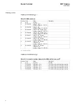
Table 4: Thermal load capacity
Quantity
Range
Current path
250 x I
n
(peak value),
100 x I
n
for 1 s (dynamic ),
5 x I
n
(continuous)
Voltage path
2 x U
n
/
√
3 (continuous)
Table 5: Consumption
Quantity
Range
Current path
<0.1 VA at I
n
Voltage path
<0.25 VA at U
n
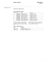
Table 6: ANSI code protection functions and parameters
Current protection functions
68
Inrush stabilization (Only in
connection with 50 and 51)
N = 2.0 - 8.0
M = 3.0 - 4.0
Time = 200 -100 000 ms
68
Inrush harmonic
Minimum current threshold = 0.05 - 40.00 x I
n
Fault current threshold = 0.05 - 40.00 x I
n
Harmonic ratio threshold = 5 - 50%
50
Overcurrent instantaneous
I>>> = 0.100 - 40.000 x I
n
t = 15 - 30 000 ms
51
Overcurrent high
I>> = 0.05 - 40.00 x I
n
t = 20 - 300 000 ms
51
Overcurrent low
I> = 0.05 - 40.00 x I
n
t = 20 - 300 000 ms
51 IDMT
Overcurrent IDMT (Inverse Definite
Minimum Time)
Inverse time characteristics: Normal, Very, Extreme
and Long-time inverse
I
e
= 0.050 - 40.000 x I
n
K = 0.050 - 1.500
Summary of Contents for REF 542plus
Page 1: ...Feeder Terminal Product Guide REF 542plus...
Page 2: ......


