12.4.8.4
Settings
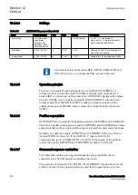
PID-6712-SETTINGS v3
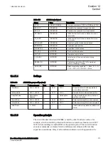
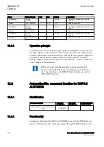
Table 203:
XLNPROXY Non group settings (basic)
Name
Values (Range)
Unit
Step
Default
Description
SwitchType
Circuit Breaker
Load Break
Disconnector
Earthing Switch
HS Earth Switch
-
-
Circuit Breaker
0 = CB, 1 = Load Break, 2 =
Disconnector, 3 = Earthing Switch, 4 =
High Speed Earthing Switch
tStartMove
0.000 - 60.000
s
0.001
0.100
Supervision time for the apparatus to
move after a command
tIntermediate
0.000 - 60.000
s
0.001
0.150
Allowed time for intermediate position
GUID-A4CCC681-D4D8-4534-905D-1D8AD40E923B v1
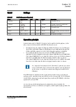
The default values of the inputs BEH, OPCNT, EEHEALTH and
OPCAP are set to -1 to denote that they are not connected.
12.4.8.5
Operation principle
GUID-D2679E0E-ABB5-46F0-AD9C-F6E8E8099534 v1
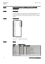
The proxy for signals from switching device via GOOSE (XLNPROXY) is
intended to be used when the switch (XCBR) is modelled and controlled in a
breaker IED or similar unit on the process bus. XLNPROXY packages the signals
from the GOOSE receive function, normally GOOSEXLNRCV, into the same
format as used from SXCBR to SCSWI. It makes a similar evaluation of the
command response as SXCBR when a command is issued from the connected
SCSWI.
12.4.8.6
Position supervision
GUID-95C72346-A577-4F0A-8584-8E1593B9B947 v1
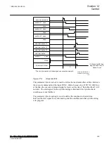
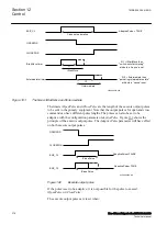
XLNPROXY has two outputs for position indication: OPENPOS and CLOSEPOS.
Position is a double point indication and the OPENPOS and CLOSEPOS are binary
outputs intended to be used for condition logics to protection and control functions
Normally, the position outputs, OPENPOS and CLOSEPOS, follow the value of
the input POSVAL. However, if the POSVAL_V input is FALSE, the
communication is lost (COMMVALID = FALSE), or the quality of the position
received is bad, the OPENPOS and CLOSEPOS are both set to FALSE.
12.4.8.7
Command response evaluation
GUID-A2CDC1AE-A6F5-478B-B6E5-3442C54212D8 v1
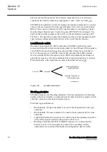
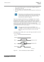
The command evaluation is triggered through the group input XIN that is
connected to the SCSWI function controlling the switch.
If an operation is initiated by the SCSWI, the XLNPROXY function checks if the
switch is blocked for the operation direction and that the position moves to the
Section 12
1MRK 505 394-UEN A
Control
380
Line differential protection RED650 2.2 IEC
Technical manual
Summary of Contents for RED650
Page 1: ...RELION 650 SERIES Line differential protection RED650 Version 2 2 Technical manual...
Page 2: ......
Page 36: ...30...
Page 46: ...40...
Page 232: ...226...
Page 272: ...266...
Page 288: ...282...
Page 306: ...300...
Page 406: ...400...
Page 436: ...430...
Page 502: ...496...
Page 614: ...608...
Page 628: ...622...
Page 644: ...638...
Page 760: ...754...
Page 778: ...772...
Page 814: ...808...
Page 870: ...864...
Page 874: ...868...
Page 924: ...918...
Page 925: ...919...


