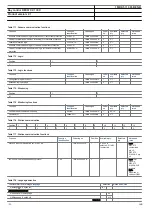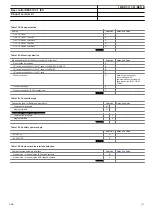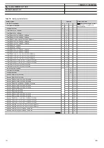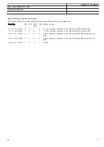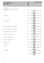
Binary input/output module, mA and time synchronizating
boards.
#11
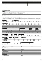
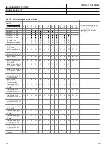
Notes and Rules
For pulse counting, for example kWh metering, the BIM with enhanced pulse counting capabilities must be used.
Note: 1BIM and 1 BOM included in A30 and A31. 2 BIM and 1 BOM included in B30 and C30.
Slot position (rear view)
X31
X41
X51
X61
X71
X81
X91
X101
X111
X121
X131
X141
X151
X161
Note: Max 3 positions in 1/2 rack,
8 in 3/4 rack with 1 TRM, 5 in 3/4
rack with 2 TRM, 14 in 1/1 rack
with 1 TRM and 11 in 1/1 rack
with 2 TRM
1/2 Case with 1 TRM
█
█
█
3/4 Case with 1 TRM
█
█
█
█
█
█
█
█
3/4 Case with 2 TRM
█
█
█
█
█
1/1 Case with 1 TRM
█
█
█
█
█
█
█
█
█
█
█
█
█
█
1/1 Case with 2 TRM
█
█
█
█
█
█
█
█
█
█
█
No board in slot
X
X
X
X
X
X
X
X
X
X
X
X
X
X
Binary output module 24 output relays (BOM)
A
A
A
A
A
A
A
A
A
A
A
A
A Note: Maximum 4 (BOM+SOM
+MIM) boards. X51 not in B30/
C30.
BIM 16 inputs, RL24-30 VDC, 50 mA
B
1
B
1
B
1
B
1
B
1
B
1
B
1
B
1
B
1
B
1
B
1
B
1
B
1
BIM 16 inputs, RL48-60 VDC, 50 mA
C
1
C
1
C
1
C
1
C
1
C
1
C
1
C
1
C
1
C
1
C
1
C
1
C
1
BIM 16 inputs, RL110-125 VDC, 50 mA
D
1
D
1
D
1
D
1
D
1
D
1
D
1
D
1
D
1
D
1
D
1
D
1
D
1
BIM 16 inputs, RL220-250 VDC, 50 mA
E
1
E
1
E
1
E
1
E
1
E
1
E
1
E
1
E
1
E
1
E
1
E
1
E
1
BIM 16 inputs, 220-250 VDC, 120mA
E
2
E
2
E
2
E
2
E
2
E
2
E
2
E
2
E
2
E
2
E
2
E
2
E
2
BIMp 16 inputs, RL24-30 VDC, 30 mA, for pulse counting
F
F
F
F
F
F
F
F
F
F
F
F
Note: X51 not in B30/C30.
BIMp 16 inputs, RL48-60 VDC, 30 mA, for pulse counting
G G G G G G G G G G G G
BIMp 16 inputs, RL110-125 VDC, 30 mA, for pulse counting
H H
H H H H H H H H H H
BIM 16 inputs, RL220-250 VDC, 30 mA, for pulse counting
K
K
K
K
K
K
K
K
K
K
K
K
IOM 8 inputs, 10+2 output, RL24-30 VDC, 50 mA
L
1
L
1
L
1
L
1
L
1
L
1
L
1
L
1
L
1
L
1
L
1
L
1
IOM 8 inputs, 10+2 output, RL48-60 VDC, 50 mA
M
1
M
1
M
1
M
1
M
1
M
1
M
1
M
1
M
1
M
1
M
1
M
1
IOM 8 inputs, 10+2 output, RL110-125 VDC, 50 mA
N
1
N
1
N
1
N
1
N
1
N
1
N
1
N
1
N
1
N
1
N
1
N
1
IOM 8 inputs, 10+2 output, RL220-250 VDC, 50 mA
P
1
P
1
P
1
P
1
P
1
P
1
P
1
P
1
P
1
P
1
P
1
P
1
IOM 8 inputs 10+2 output relays, 220-250 VDC, 110mA
P
2
P
2
P
2
P
2
P
2
P
2
P
2
P
2
P
2
P
2
P
2
P
2
IOM with MOV 8 inputs, 10-2 output, 24-30 VDC, 30 mA
U U
U U U U U U U U U U
IOM with MOV 8 inputs, 10-2 output, 48-60 VDC, 30 mA
V
V
V
V
V
V
V
V
V
V
V
V
IOM with MOV 8 inputs, 10-2 output, 110-125 VDC, 30 mA
W W W W W W W W W W W W
IOM with MOV 8 inputs, 10-2 output, 220-250 VDC, 30 mA
Y
Y
Y
Y
Y
Y
Y
Y
Y
Y
Y
Y
mA input module MIM 6 channels
R R
R R R R R R R R R R Note: maximum 1 MIM in 1/2
case.
X51 not in B30/C30.
SOM Static output module, 12 outputs, 48-60 VDC
T
1
T
1
T
1
T
1
T
1
T
1
T
1
T
1
T
1
T
1
T
1
T
1
Note: SOM must not to be placed
in position nearest to NUM; 1/2
case slot P5, 3/4 case 1 TRM slot
P10, 3/4 case 2 TRM slot P7, 1/1
case 1 TRM slot P16, 1/1 case 2
TRM slot P13
X51 not in B30/C30.
SOM static outputs module, 12 outputs, 110-250 VDC
T
2
T
2
T
2
T
2
T
2
T
2
T
2
T
2
T
2
T
2
T
2
T
2
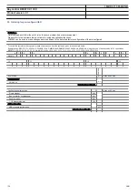
Selection for position #11.
1MRK 511 361-BEN B
Bay control REC670 2.1 IEC
Product version: 2.1
ABB
109
Summary of Contents for REC670 2.1 IEC
Page 1: ...Relion 670 series Bay control REC670 2 1 IEC Product guide ...
Page 115: ...115 ...

