


4.2.4.1
Example
Consider a VT with the following data:
132kV 120V
3
3
EQUATION1937 V1 EN
(Equation 21)
The following setting should be used:
VTprim=132
(value in kV)
VTsec=120
(value in V)
4.2.4.2
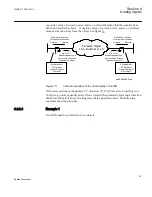
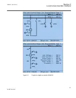
Examples how to connect, configure and set VT inputs for most commonly
used VT connections
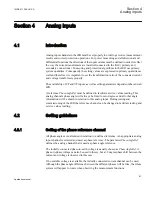
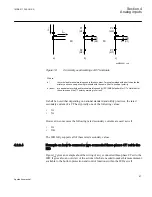
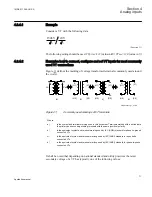
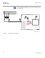
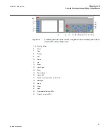
Figure
defines the marking of voltage transformer terminals commonly used around
the world.
A
(H1)
B
(H2)
b
(X2)
a
(X1)
A
(H1)
N
(H2)
n
(X2)
a
(X1)
b)
c)
A
(H1)
N
(H2)
dn
(X2)
da
(X1)
d)
V
Pri
+
+
V
Sec
a)
ANSI11000175_1_en.vsd
ANSI11000175 V1 EN
Figure 21:
Commonly used markings of VT terminals
Where:
a)
is the symbol and terminal marking used in this document. Terminals marked with a dot indicate
the primary and secondary winding terminals with the same (positive) polarity
b)
is the equivalent symbol and terminal marking used by IEC (ANSI) standard for phase-to-ground
connected VTs
c)
is the equivalent symbol and terminal marking used by IEC (ANSI) standard for open delta
connected VTs
d)
is the equivalent symbol and terminal marking used by IEC (ANSI) standard for phase-to-phase
connected VTs
It shall be noted that depending on national standard and utility practices the rated
secondary voltage of a VT has typically one of the following values:
1MRK 511 286-UUS A
Section 4
Analog inputs
71
Application manual
Summary of Contents for REC650 ANSI
Page 1: ...Relion 650 series Bay control REC650 ANSI Application manual...
Page 2: ......
Page 26: ...20...
Page 66: ...Section 3 1MRK 511 286 UUS A REC650 setting examples 60 Application manual...
Page 71: ...IED IED ANSI05000460 V2 EN 1MRK 511 286 UUS A Section 4 Analog inputs 65 Application manual...
Page 82: ...76...
Page 92: ...86...
Page 170: ...164...
Page 176: ...170...
Page 274: ...268...
Page 288: ...282...
Page 350: ...344...
Page 369: ...363...


