


3.1.8
Calculating settings for HV-side breaker failure protection,
CCRBRF (50BF)
The breaker failure protection can use either the position indication of the circuit breaker
or measure the current going through the CT in order to detect correct breaker functioning.
For transformer protections it is most suitable to use current measurement as a circuit
breaker failure check.
1.
Set
GlobalBaseSel
to
1
The (HV) winding data should be related to Global base 1.
2.
Set
FunctionMode
to
Current
3.
Set
BuTripMode
to
1 out of 4
The current measurement function uses the three-phase currents from the line CT
and either, a measured residual current or a calculated 3I0. Based on this analogue
data one of the following rules can be chosen in order to determine a breaker failure:
•
1 out of 3
: at least one of the three-phase current shall be larger than the set level
to detect failure to break
•
1 out of 4
: at least one of the three-phase current and the residual current shall
be larger than the set level to detect failure to break
•
2 out of 4
: at least two of the three-phase current and the residual current shall
be larger than the set level to detect failure to break.
As the residual current protection is one of the protection functions to initiate the
breaker failure protection the setting
1 out of 4
is chosen.
4.
Set
Pickup_PH
to
20 %
of
IBase
Pickup_PH
should be set lower than the smallest current to be detected by the
differential protection which is set 30% of
IBase
.
5.
Set
Pickup_N
to
20 %
of
IBase
Pickup_N
should be set lower than the smallest current to be detected by the most
sensitive step of the residual ovecurrent protection which is 100 A.
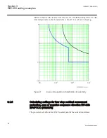
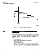
6.
Set the re-tip time delay
t1
to
0
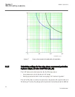
7.
Set
t2
to
0.17 s
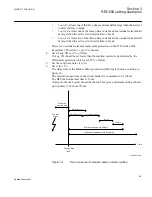
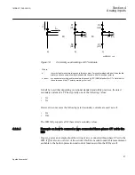
The delay time of the breaker failure protection (BuTrip) is chosen according to
figure
.
The maximum opening time of the circuit breaker is considered to be 100 ms.
The breaker failure protection BFP maximum reset time is 15 ms.
A margin of about 2 cycles should be chosen. This gives a minimum setting of back-
up trip delay
t2
of about 155ms.
1MRK 511 286-UUS A
Section 3
REC650 setting examples
57
Application manual
Summary of Contents for REC650 ANSI
Page 1: ...Relion 650 series Bay control REC650 ANSI Application manual...
Page 2: ......
Page 26: ...20...
Page 66: ...Section 3 1MRK 511 286 UUS A REC650 setting examples 60 Application manual...
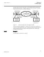
Page 71: ...IED IED ANSI05000460 V2 EN 1MRK 511 286 UUS A Section 4 Analog inputs 65 Application manual...
Page 82: ...76...
Page 92: ...86...
Page 170: ...164...
Page 176: ...170...
Page 274: ...268...
Page 288: ...282...
Page 350: ...344...
Page 369: ...363...


