


Section 3
REC650 setting examples
3.1
Setting example when REC650 is used as back-up
protection in a transformer protection application
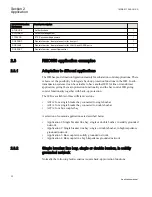
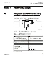
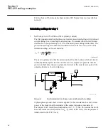
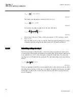
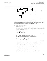
The application example has a 145/22 kV transformer as shown in figure
.
1
1
1
3
3
Ph-Ph
145 kV
22 kV
ANSI11000121-1-en.vsd
REC650
Y
Y
Y
ANSI11000121 V1 EN
Figure 5:
Two-winding HV/MV transformer, Y/Δ-transformer
Table 3:
Typical data for the transformer application
The following data is assumed:
Item
Data
Transformer rated power SN
60 MVA
Transformer high voltage side rated voltage VN1
145 kV ±9 · 1.67 % (with on load tap changer)
Transformer low voltage side rated voltage VN2
22 kV
Transformer vector group
YNd11
Transformer impedance voltage at tap changer mid
point: ek
12 %
Maximum allowed continuous overload
1.30 · SN
Phase CT ratio at 145 kV level
300/1 A
CT at 145 kV neutral
300/1 A
Phase CT ratio at 22 kV level
2 000/1 A
22 kV VT ratio
/
22
3
0 11
3
.
0 11
3
.
/
kV
Table continues on next page
1MRK 511 286-UUS A
Section 3
REC650 setting examples
39
Application manual
Summary of Contents for REC650 ANSI
Page 1: ...Relion 650 series Bay control REC650 ANSI Application manual...
Page 2: ......
Page 26: ...20...
Page 66: ...Section 3 1MRK 511 286 UUS A REC650 setting examples 60 Application manual...
Page 71: ...IED IED ANSI05000460 V2 EN 1MRK 511 286 UUS A Section 4 Analog inputs 65 Application manual...
Page 82: ...76...
Page 92: ...86...
Page 170: ...164...
Page 176: ...170...
Page 274: ...268...
Page 288: ...282...
Page 350: ...344...
Page 369: ...363...


