


function as well as different time delay characteristics. It is important to base the
setting on fault calculations considering different operational states as well as time
delay coordination with other protections in the system.
•
Failure of the circuit beaker to interrupt fault current after protection trip. The breaker
failure protection function is essential in a protection system using local redundancy.
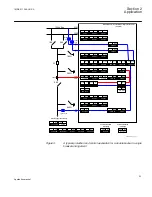
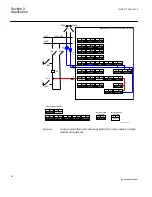
2.3.5
Bus coupler in a high impedance grounded network
Normally the following fault scenarios require back-up protection functions:
•
Short circuits on one of the busbar sections and short circuits on outgoing lines. For
these faults the four step phase overcurrent protection should be used. The four step
phase overcurrent protection has the possibility of directional function as well as
different time delay characteristics. It is important to base the setting on fault
calculations considering different operational states as well as time delay co-
ordination with other protections in the system.
•
Phase-to-ground faults. In high impedance grounded networks the fault current at a
single phase-to-ground fault is small. For these faults the sensitive residual
overcurrent protection should be used. The sensitive residual overcurrent protection
has the possibility of directional function. It is important to base the setting on fault
calculations considering different operational states as well as time delay co-
ordination with other protections in the system. As a second protection a residual
voltage protection is often used.
•
Failure of the circuit beaker to interrupt fault current after protection trip. The breaker
failure protection function is essential in a protection system using local redundancy.
•
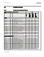
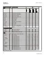
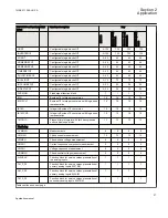
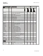
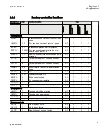
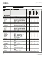
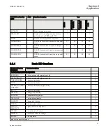
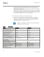
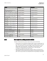
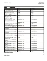
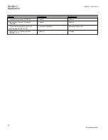
Enabled: It is recommended to have the function activated in the application
•
Disabled: It is recommended to have the function deactivated in the application
•
Application dependent.: The decision to have the function activated or not is
dependent on the specific conditions in each case
Application 3 and Application 4 in table
examples given in previous sections.
Section 2
1MRK 511 286-UUS A
Application
36
Application manual
Summary of Contents for REC650 ANSI
Page 1: ...Relion 650 series Bay control REC650 ANSI Application manual...
Page 2: ......
Page 26: ...20...
Page 66: ...Section 3 1MRK 511 286 UUS A REC650 setting examples 60 Application manual...
Page 71: ...IED IED ANSI05000460 V2 EN 1MRK 511 286 UUS A Section 4 Analog inputs 65 Application manual...
Page 82: ...76...
Page 92: ...86...
Page 170: ...164...
Page 176: ...170...
Page 274: ...268...
Page 288: ...282...
Page 350: ...344...
Page 369: ...363...


