


Event recorder
Event recorder function has no dedicated parameters.
Trip value recorder
ZeroAngleRef
: The parameter defines which analog signal that will be used as phase angle
reference for all other analog input signals. This signal will also be used for frequency
measurement and the measured frequency is used when calculating trip values. It is
suggested to point out a sampled voltage input signal, for example, a line or busbar phase
voltage (channel 1-30).
Sequential of events
function has no dedicated parameters.
12.7.3.4
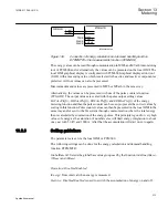
Consideration
The density of recording equipment in power systems is increasing, since the number of
modern IEDs, where recorders are included, is increasing. This leads to a vast number of
recordings at every single disturbance and a lot of information has to be handled if the
recording functions do not have proper settings. The goal is to optimize the settings in each
IED to be able to capture just valuable disturbances and to maximize the number that is
possible to save in the IED.
The recording time should not be longer than necessary (
PostFaultrecT
and
TimeLimit
).
•
Should the function record faults only for the protected object or cover more?
•
How long is the longest expected fault clearing time?
•
Is it necessary to include reclosure in the recording or should a persistent fault
generate a second recording (
PostRetrig
)?
Minimize the number of recordings:
•
Binary signals: Use only relevant signals to start the recording that is, protection trip,
carrier receive and/or pickup signals.
•
Analog signals: The level triggering should be used with great care, since unfortunate
settings will cause enormously number of recordings. If nevertheless analog input
triggering is used, chose settings by a sufficient margin from normal operation values.
Phase voltages are not recommended for trigging.
Remember that values of parameters set elsewhere are linked to the information on a
report. Such parameters are, for example, station and object identifiers, CT and VT ratios.
1MRK 511 286-UUS A
Section 12
Monitoring
301
Application manual
Summary of Contents for REC650 ANSI
Page 1: ...Relion 650 series Bay control REC650 ANSI Application manual...
Page 2: ......
Page 26: ...20...
Page 66: ...Section 3 1MRK 511 286 UUS A REC650 setting examples 60 Application manual...
Page 71: ...IED IED ANSI05000460 V2 EN 1MRK 511 286 UUS A Section 4 Analog inputs 65 Application manual...
Page 82: ...76...
Page 92: ...86...
Page 170: ...164...
Page 176: ...170...
Page 274: ...268...
Page 288: ...282...
Page 350: ...344...
Page 369: ...363...


