


12.4.4.1
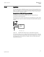
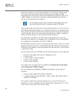
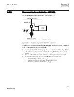
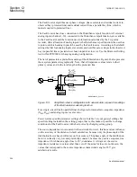
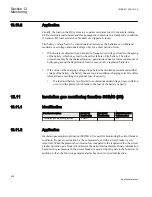
Measurement function application for a 380kV OHL
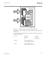
Single line diagram for this application is given in figure
380kV Busbar
380kV OHL
P
Q
800/5 A
ANSI09000039-1-en.vsd
380kV 120V
/
3 3
kV
IED
ANSI09000039 V1 EN
Figure 133:
Single line diagram for 380kV OHL application
In order to monitor, supervise and calibrate the active and reactive power as indicated in
figure
it is necessary to do the following:
1. Set correctly CT and VT data and phase angle reference channel
PhaseAngleRef
(see
settings for analog input modules in PCM600) using PCM600 for analog input
channels
2. Connect, in PCM600, measurement function to three-phase CT and VT inputs
3. Set under General settings parameters for the Measurement function:
•
general settings as shown in table
.
•
level supervision of active power as shown in table
.
•
calibration parameters as shown in table
.
1MRK 511 286-UUS A
Section 12
Monitoring
291
Application manual
Summary of Contents for REC650 ANSI
Page 1: ...Relion 650 series Bay control REC650 ANSI Application manual...
Page 2: ......
Page 26: ...20...
Page 66: ...Section 3 1MRK 511 286 UUS A REC650 setting examples 60 Application manual...
Page 71: ...IED IED ANSI05000460 V2 EN 1MRK 511 286 UUS A Section 4 Analog inputs 65 Application manual...
Page 82: ...76...
Page 92: ...86...
Page 170: ...164...
Page 176: ...170...
Page 274: ...268...
Page 288: ...282...
Page 350: ...344...
Page 369: ...363...


